Home Blog

A River Reborn

Fort Worth’s Central City project channels the flood-prone Trinity River to protect one of the country’s fastest-growing cities

The U.S. Army Corps of Engineers’ warning to Fort Worth was clear: Fix the Trinity River floodway as it flows through downtown or run the risk of being hit with a devastating flood.

That dire warning from the late 1980s ignited communitywide soul-searching about how to protect the city from a sweeping natural disaster while embracing the Trinity River and enhancing the city’s quality of life.

From that debate came the Central City Flood Control project, an ambitious collaborative effort by federal, state, and local governments to provide Fort Worth with improved flood protection by rechanneling the river.

The multifaceted flood control project also inspired a rediscovery of the Trinity River as a community asset. The project is creating an island prime for development. It is reimagining parks and expanding riverside trails. And it is restoring wildlife habitats and removing hazardous wastes.

Local historian, attorney, and probate judge Quentin McGown describes the river’s transformation from a drainage ditch to a thriving asset as nothing less than amazing. “It’s the artery. It’s the reason the community exists,” he says. “It is the one thing that ties the entirety of the city and the region together.”

Protecting a Growing City

Concerns about flooding along the Trinity River go back to the 1930s. A 1942 flood swamped the Fort Worth Stockyards. The big flood came in 1949, when 11 inches of rain fell on the city in nine hours, turning the Trinity River into a 14-block-wide body of water that killed 10 people and left 13,000 homeless.

The U.S. Army Corps of Engineers and the Tarrant Regional Water District (TRWD) eventually responded to that threat by constructing a 27-mile levee system with floodgates and low-water dams to contain flows near the central business district. That system went largely unchanged for 55 years.

The surrounding conditions have changed, however; Fort Worth has experienced significant growth. Its population has soared from 350,000 when the levees were built to more than 1 million today. Rapid growth and increased development have resulted in higher flood levels during major storm events.

If flooding similar to the recent devastating events in central Texas were to occur in Fort Worth today, it could potentially overcome the current levee system, causing widespread damage to one of the nation’s fastest-growing cities.

Designing New Flood Controls

Federal, state, and local agencies and private concerns have studied how to improve conditions along the Trinity River over the years, and about 200 public meetings were held from 2001–2005 to discuss plans for the river.

The Army Corps approved a final design for central Fort Worth in 2008, anticipating population growth and setting the project’s flood control goals. Advancements in hydrologic modeling and meteorology have since been applied to the final design, but the scope of the planned flood protections stayed the same.

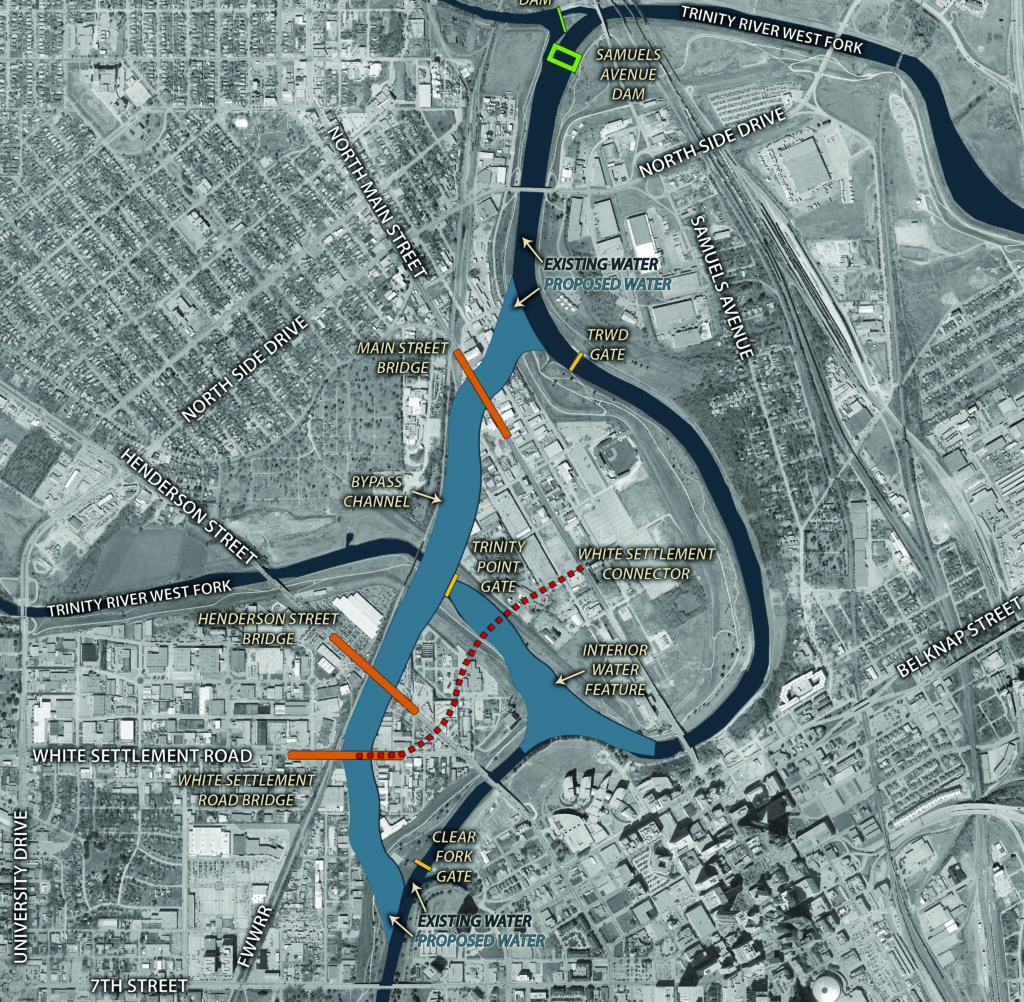
The Central City Flood Control Project involves the construction of a 1.5 mi
(2.4 km) bypass channel that reroutes floodwaters from the Trinity River (Fig. 5). Redirecting the river’s Clear Fork and West Fork through the channel lowers water levels, helping the existing levee system manage the flow more efficiently and providing added flood protection for the community.

The Riverside Oxbow and Gateway Park on the city’s east side were wrapped into the Central City plan as a way to move flood storage from largely privately held land on the city’s west side. The ambitious, innovative design also created Panther Island north of downtown, which is currently under development. Once completed, the project will protect an area that has become significantly more populated since the original levee system was built.

Getting to Shovel-Ready

Requests for bids for the northern section of the bypass channel issued in April, and the contract will be awarded in August. After almost two decades of planning, construction on the key element of the Central City flood control project is expected to begin in the fall.

“We’ve been talking about this for 20 years,” says Tarrant Regional Water District Central City Flood Control Project Manager Kelly Wood. “Now it’s here. Things are moving quickly.”

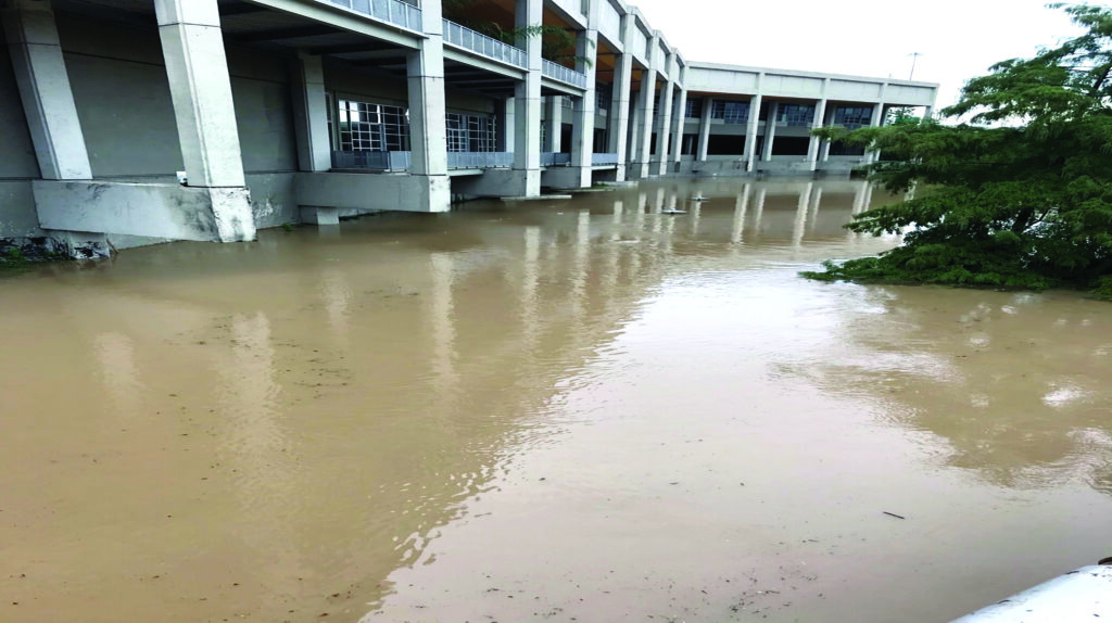
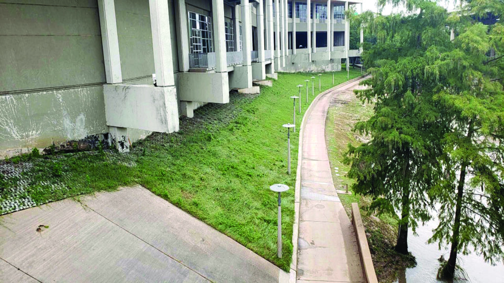
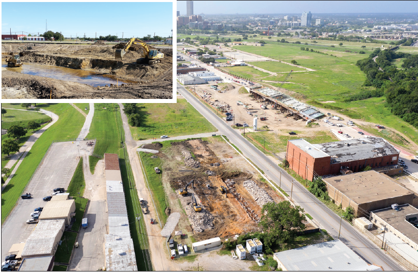
Before work can actually begin on the bypass channel, however, local partners needed to have most of the area in a “shovel-ready” state. TRWD has already removed more than 400,000 tons of contaminated soil and treated more than 44 million gallons of tainted groundwater (Figs. 6-7). The cleanup was required because the work is being done in a part of the city where many structures have been abandoned and forgotten, presenting unique environmental challenges.

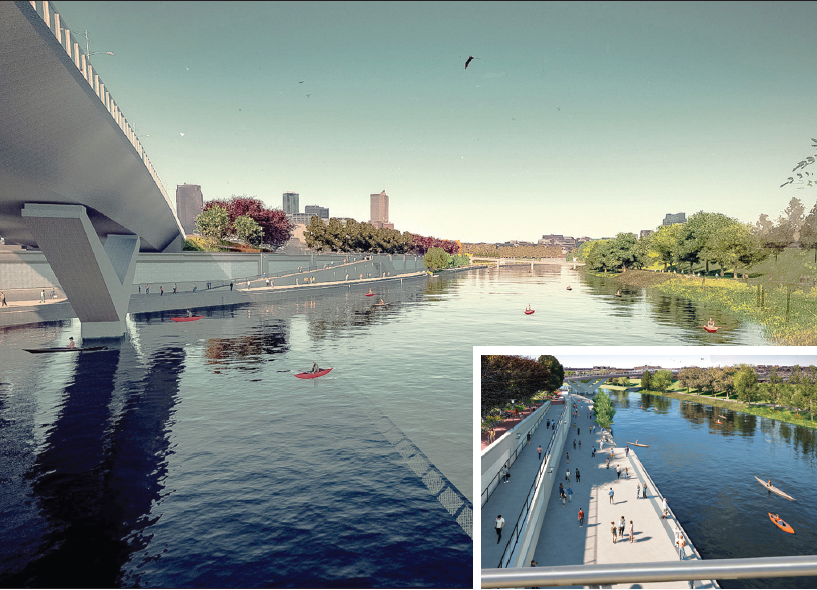
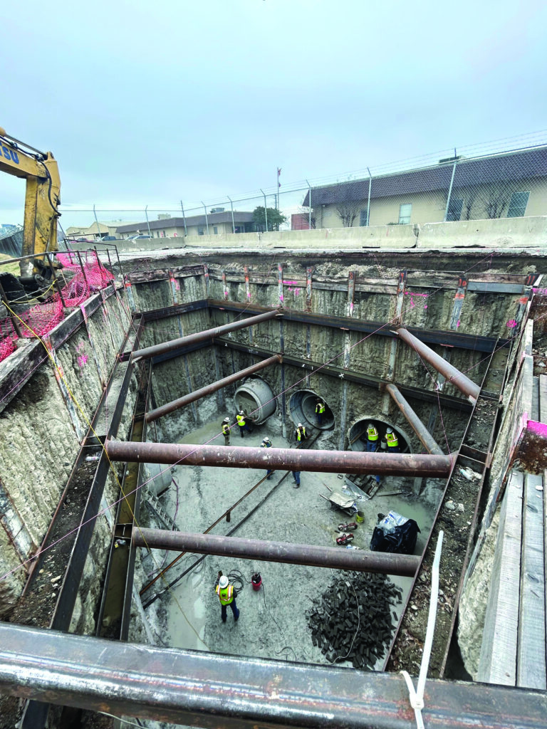
To meet Army Corps requirements, three gleaming new bridges have been built over dry land on Henderson, North Main, and West Side Drive to connect Panther Island to the rest of the city (Figs. 1-2). All existing storm drainage systems and other structures in the path of the bypass channel also had to be removed and relocated. Adding complexity to that task was the creation of 16 tunnels, some of which will run under the proposed bypass channel and the levee system (Fig. 8). Several were installed underneath railroad tracks.

Figs. 1-2: Construction proceeds on the bridges connecting the newly created Panther Island to the rest of the city.

While there was nothing unusual about the tunnel construction methods used, the Army Corps sent a world-class tunnel expert from Boston to inspect the work. Anything that gets too close to the existing levee system and the bypass channel must be completely vetted.

Figs. 3-4: Renderings of the new bypass channel show how the Central City project will reinvent the Trinity River into a recreational asset while
directing floodwaters away from development.

“Anything that passes over, through, and under the levee gets a lot of scrutiny to see if it introduces a problem, to make sure we’re not doing anything with unintended consequences,” Wood says. “Everyone is feeling the pressure, and that’s not a bad thing. Everyone is sensing the urgency of it.”

Fig. 5: The project will redirect floodwaters through a bypass channel to protect the community from flooding.

Better Than a Ditch

McGown and others joke that the TRWD, the Army Corps, and the City of Fort Worth could have just built a drainage ditch. And when the current Fort Worth floodway and levee system was completed in the 1970s, that’s what many people felt they got.

Figs. 6-7: The channel cuts through an area where many structures have been abandoned and require remediation.

The high levees closed the Trinity River off from citizens. Its banks were covered in litter, and the river was seen as toxic. “When I was growing up, the Trinity River was nasty,” McGown says. “No one wanted to go to the river. It was a flood control project, not a river intended for public pleasure.”

McGown is excited about the ecological mitigation and environmental remediation work that has been performed as a result of the Central City project. TRWD adopted a Water Quality Guidance Manual for enhanced stormwater quality practices in 2018, for example, that introduced landowners and developers to green infrastructure options such as rain gardens and bioswales that keep runoff from simply going down the drain. It also provides examples of structures such as underground sand filters and bioretention basins, which can help deal with oil, trash, and debris in stormwater runoff.

Fig. 8: Existing utility and drainage tunnels needed to be rerouted underneath the new channel.

The Ham Branch Habitat Mitigation project on the eastern edge of Central City will turn an urban stream into a thriving wetland ecosystem inside Harmon Park. TRWD is restoring 1,950 linear feet of degraded urban stream channel, reestablishing native trees and vegetation across a 7.4-acre (4.9 ha) riparian corridor and creating a small, emergent wetland.

On the western edge of Central City, TRWD is working in Rockwood Park and golf course to reconnect oxbows that have become disconnected from the river and create better habitats for wildlife and aquatic growth. At the same time, the district is excavating 23 acres of land to control floodwaters and provide crucial valley storage.

The Central City Flood Control Project will provide Fort Worth with the flood protection it needs while giving citizens a river it loves. “It gives the river back—and the public wants the river back,” Wood says.

A lot of work remains to be done, but McGown foresees the river’s rebirth. “As you drive over the dryland bridges, you can squint your eyes and see what it’s going to be like finally,” he says. “It’s a pretty exciting future.” n

About the Experts

Matt Oliver is communication manager at Tarrant Regional Water District.

Max B. Baker is a Fort Worth-based, award-winning journalist who worked for the Tarrant Regional Water District for eight years.

Elements of the Plan

The federal Central City Flood Control Project includes the following:

  • A 1.5-mile bypass channel that will reroute floodwaters near the downtown area;
  • Floodwater storage sites to slow the water entering the channel and prevent flooding to the east;
  • Three floodgates;
  • Three vehicular bridges at Main St., Henderson St., and White Settlement Road;
  • A pumping station; and
  • The Samuels Ave. Dam.

Better Than Rocks and Walls

Two sustainable, habitat-friendly solutions are helping protect coastlines

“Mother Nature does it best.” That’s what I have told developers, municipalities, and designers for years when crafting green infrastructure solutions to manage stormwater runoff. Now, solutions that use vegetation and marine habitat to protect coastlines have inspired a pivot away from less effective, “gray” infrastructure methods such as seawalls and rock revetments.

The importance of this shift toward innovative green infrastructure stormwater solutions can’t be overstated. According to the National Oceanic and Atmospheric Administration (NOAA) U.S. Climate Resilience Toolkit, coastal erosion is responsible for roughly $500 million of damage per year in coastal property loss, including harm to structures and loss of land.

Historically, coastal communities have constructed low sills or breakwaters to reduce wave energy before it can impact the shoreline—typically by stacking rocks. Unfortunately, rock structures move over time; they can be difficult to install; they offer little benefit to the marine environment; and transporting them to a project site can have negative environmental impacts. Moreover, rock walls between the shore and larger body of water can fragment the rhythms of the natural ecosystem.

New Solutions

Innovative manufactured solutions can now replace the rock walls used in breakwater applications, however. Newly engineered products mimic natural breakwater designs such as oyster sills and native vegetation, supporting the ecosystem rather than disrupting it. Such products reduce coastal erosion, provide habitat for marine life, and create an opportunity for vegetation to establish itself upland.

Two products can deliver effective protection: Reef Arches® and Natrx ExoForms®. Reef Arches’ 1,200-pound (544 kg) arch-shaped design (Fig. 1) incorporates an open base proven to reduce scour and erosion when compared to solid-based structures, making them an effective option for hard and sandy-bottom aquatic areas. Openings throughout the arch allow water to flow through while simultaneously calming wave energy, promoting sediment accretion. Reef Arches connect into a single heavy structure using fiberglass-reinforced plastic panels, ensuring the strength required to withstand strong storm events.

Fig. 1: Reef Arches form a breakwater to protect the shoreline.

Precast Reef Arches use basalt rebar rather than traditional steel to create an unusual shape that’s built to withstand harsh marine conditions over time. Manufacturing uses a combination of sand and calcium sulfoaluminate (CSA) cement; the neutral pH allows mollusks such as oysters and clams to grow safely on the surface alongside coral.

Each unit offers approximately 120 ft2 (11.1 m2) of surface area for marine habitat while maintaining ample space for fish and other marine life to search for the benthic infauna living in the substrate beneath it. The flourishing habitat also attracts birds eager to feed.

Another Solution

Natrx ExoForms (Fig. 2) are also built to dissipate wave energy and support thriving marine ecosystems. Made of concrete, they are available in weights ranging from 30-lb (13.6-kg), hand-deployable units to 2,000-lb (907-kg) products for high wave-energy applications.

Natrx ExoForms’ designs offer stability on soft soils, making them an excellent choice for marshy areas. The 3D-printed, precision-manufactured modules mimic nature, with naturalistic surfaces that offer voids and textures marine organisms can quickly colonize. The sustainable infrastructure performs better as the habitat gets established, and Natrx ExoForms blend seamlessly into their surroundings.

Fig. 2: The Natrx Fish House Habitat helps create a living shoreline.

WaveBrush ExoForms function as a low-relief solution for use in shallow, low-wave-energy waters that captures sediment and stabilizes soft banks while giving the appearance of cypress tree knees on the surface. A sloped design for energetic shorelines provides a natural appearance that blends into the landscape.

Habitat ExoForms include the Crabitat, which allows water to flow through, promoting accretion while providing refuge to fish and crustaceans. The pH-neutral materials also enable mollusks and coral to safely make these structures their home.

Easy Installation

Manufactured structures are often easier and faster to install than large rocks, offering modular designs that are easy for contractors to manage. They are typically put in place using a small crane or backhoe from a barge or from land; smaller options can be placed by hand. It is not necessary to anchor a Reef Arch or ExoForm, since their weight is sufficient to keep them in place. This allows for straightforward installation—just lift and place.

Manufactured solutions can offer additional efficiencies over traditional rock walls. Most large rocks come from quarries hundreds of miles from a project site; they are extracted using explosives and loaded onto trucks or barges for delivery. The modular designs of Reef Arches and Natrx ExoForms, on the other hand, allow them to be stacked during transport, reducing fuel use and creating a smaller carbon footprint. They can also speed installation, saving contractors time and often reducing project costs.

Project goals and site conditions will determine which product to use. Ask the following:

  • What is the composition of the subsoils?
  • What are the expected wave conditions for wind fetch and designed storms?
  • What are the hydraulic conditions including tidal patterns, water depth, and future sea levels?
  • Is the goal to accrete sediment or retain what’s currently present?
  • Is there submerged aquatic vegetation (SAV) in the area?
  • How will the shoreline be used? Will there be recreational access?
  • Are there specific marine conditions you want to leverage in the area?

Using the appropriate product in the right place is critical to project success. When considering installation areas, ask the manufacturer to provide information about their products or ask your local distributor.

With sea level rise and increased storm frequency and intensity, coastal communities are facing increased threats to their coastlines. Most government agencies recognize the threat and spend billions to repair, replace, and build new coastal infrastructure.

Gray infrastructure’s value peaks on Day One; seawalls start degrading upon installation, and rocks move with wave energy. In contrast, living shorelines get stronger and more resilient over time.

Manufactured structures such as Reef Arches and Natrx Exoforms work with nature, leveraging the benefits of marine habitat and native vegetation. With correct implementation, such products can fade into the landscape and protect shorelines, leaving a legacy for generations.

About the Expert

Chris Bogdan is green stormwater infrastructure manager for Ferguson Waterworks.

Here Comes the Sun

Start stormwater management at the
beginning of a solar project to prevent erosion

Stormwater and erosion control are significant considerations for infrastructure development projects, and large acreages are now being converted to utility-scale solar farms as energy demand increases. On solar projects where the previous land use is not perennial grassland such as row-crop agriculture or forestry, strategic planning for stormwater management is critical due to large areas of bare ground.

By implementing innovative science and agricultural-based techniques, not only will stormwater design be more successful, but overall costs will be lower due to fewer failures and expedited permit closure.

Limited Access

Unlike linear or underground projects, where restoration can be performed effectively after project completion, solar restoration poses a challenge due to limited equipment access in and around panels. By rearranging the traditional project timeline and starting restoration at the beginning of a project, stormwater risk can be lowered significantly.

Traditional sediment and erosion control plans rely heavily on temporary and perimeter controls to manage erosion and prevent off-site deposition. This can be effective on smaller drainage areas, but utility-scale solar sites often span hundreds of acres. It isn’t practical or effective to have controls break up the landscape and inhibit equipment traffic. This also exposes large areas of ground and offers stormwater longer distances to travel, channelize, and cause erosion (Figs. 1-2).

Fig. 1-2: Erosion occurs quickly on solar farms installed on bare land.

The implementation of restoration as part of the civil phase of construction allows vegetation to establish concurrently with construction (Fig. 3). Not only does this reduce the restoration scope at the end of the project, it also lessens the total erosion potential during the construction phase significantly. As vegetation grows and covers the soil surface, the erosion potential or “R-factor” decreases.

Fig. 3: Seeding early in an infrastructure project helps vegetation get established.

The R-factor and other characteristics, such as surface roughness, slope, and soil type, are important considerations for determining a project’s erosion control and stormwater basin design. In instances where minimal grading is needed for tracker design, a solar site can be fully seeded prior to construction. If a site is fully vegetated (Fig. 4), the footprint of—or the need for—temporary controls such as basins can be reduced. Additionally, both growing and established vegetation reduce total erosion, minimizing maintenance burdens during construction.

Fig. 4: Established grasses slow stormwater runoff and soil erosion.

The presence of established vegetation on a site contributes to the following:

  • Reduced soil erosion from raindrop impact. The force raindrops exert when they hit the ground results in small particles of soil becoming dislodged and carried off in sheet flow.
  • Improved infiltration into the soil through root channels, resulting in less runoff.
  • Reduced occurrence of surface sealing, when clay particles disperse on the surface and prevent infiltration.
  • Improved soil drying and surface working conditions through plant evapotranspiration.
  • Reduced soil compaction and surface rutting due to root systems reestablishing soil aggregation and structure.

Find the Right Mix

Implementing restoration before construction or at its start—sometimes referred to as preconstruction seeding or preseeding—requires planning. Knowledgeable professionals such as soil scientists and restoration experts can tailor a seed mix to a site to achieve the greatest benefit.

Alongside a suitable seed mix that contains annual and perennial species, a strategic seeding plan must be developed alongside the site’s civil grading plan. Coordinating civil work, time of year, and construction milestone dates with seeding work optimizes establishment.

In order for a site to use vegetation as a primary method of erosion control, soil management must be a priority. A seed mix alone can’t overcome poor soil quality, compaction, unsuitable soil chemistry, or lack of topsoil. Mismanagement of soil is problematic when trying to establish vegetation at any point in the project timeline and particularly at the end of a project, when attempting to file for a Notice of Termination for the Construction General Permit.

Implementing restoration upfront tends to reduce the total acreage of land needing to be permanently stabilized with vegetation, in addition to decreasing overall erosion during construction. Seeding and restoration work after module installation is costly due to the need for small equipment and tractors, the increased risk of damaging solar infrastructure, and low production rates (acres seeded per day).

Additionally, seeding under solar modules is difficult and often ineffective. Early seeding work allows vegetation to become established in areas that will be difficult to access later, saving time and allowing restoration work to be concentrated in more accessible areas with faster production rates. Depending on when construction is completed on projects where reseeding is limited to access and disturbed areas rather than the whole site, stormwater permits may be able to be closed out within months of final seeding.

Additional benefits to implementing seeding and restoration activities at the start of solar construction include:

  • Reduced weed pressure during site operations. Establishing a mix of annual and perennial grasses as soon as possible crowds out weeds instead of allowing weeds to germinate on exposed soil.
  • Reduced occurrence of potential erosion warranty claims and pile scour. Soil is vulnerable to erosion after grading; vegetation holds the soil and prevents channels from forming. Erosion features are difficult and expensive to fix after module installation.
  • Improved public perception during construction.

Innovative stormwater techniques don’t need to be complicated to be effective. Looking at the big picture, adapting practices from other industries, and rearranging the traditional timeline are all that is required. Proactively preventing erosion should be at the forefront of the strategy.

Vegetation can be used as a primary erosion control on solar farm sites while helping meet requirements for final site stabilization. Soil management and early seeding result in overall reduced erosion, shorter permit timelines, and less rework on a site. n

About the Expert

Virginia K. Brown is a licensed soil scientist who has worked in the construction industry for over 15 years, primarily in oil and gas, renewables, and transmission. Her expertise spans the life cycle of a project, from initial environmental permitting and studies, to civil design and construction stormwater management, to final restoration.

Make Sediment Controls More Than Cosmetic

OLYMPUS DIGITAL CAMERA

The industry must focus on using its tools effectively

Owners pay for Stormwater Pollution Prevention Plan (SWPPP) compliance, regulators get paid to monitor SWPPPs, and contractors get paid for installing SWPPP infrastructure. Our industry is part of this system, providing education, certification, inspection, employment, and installation. But there is clear evidence of ineffective sediment controls—or at least poorly maintained sediment controls—all over the country.

Such “cosmetic” sediment control solutions are the result of poorly installed, poorly maintained, and therefore ineffective best management practices (BMPs). Inadequate design and “box-checking” by inspectors and regulators play a part. An industry that spends so much time, money, and energy on environmental protection must not allow such cosmetic BMP controls to persist.

What Makes Controls Ineffective?

Silt fences that sit on the ground, wattles and socks that have floated downstream or have a channel running underneath them, and other installations that are not constructed to direct storm water runoff into sediment pond(s) are a few examples of cosmetic controls.

If sites are inspected and reported on after every runoff event, how can these controls be left in clear violation week after week? How can designers, owners, managers, contractors, inspectors, and regulators not see dysfunctional controls when they are at a site?

This discussion also applies to sediment retention that focuses on heavier, sandy soil particles. Sand particles are the most important to retain, as large volumes contribute to accelerated erosion downstream or sediment accumulation where accumulation isn’t desired. Design is important to sediment control effectiveness, but installation and maintenance are where the rubber hits the road.

“Temporary” sediment controls means before erosion control begins, not short-term or unimportant. Most sediment retention devices should pond water for at least a few hours or retain considerable sediment after a runoff event to be effective. If they fail to do so, the control devices should be repaired or replaced in a timely manner.

Fig. 1: A properly installed and maintained silt fence allows water to pool.

Common Sediment Retention Devices

Silt fences represent the most established BMP. Inserting a fabric framework into the ground allows sedimentation to occur by ponding water upstream of the fence; different configurations allow more or less water through, and greater spacing between posts allows more stretching.

Even when a silt fence is supported to minimize stretching, clay and silt particles tend to build up and “blind” the filtering fabrics. This can create significant ponding, allowing sand and silt to settle out behind the silt fence. A properly installed and placed silt fence may blind and allow some runoff, but the majority of sand particles will settle out behind the fence and be retained on-site, making the silt fence BMP a very effective sediment-retention device.

But the majority of silt fences are not installed or maintained properly. The soil holding the silt fence base isn’t properly backfilled or gets compacted, or the fence is not placed to pond water effectively. With little or no compaction, runoff buildup and ponding will pipe underneath the silt fence and wash it out.

When a site is properly stabilized and the SWPPP BMPs are no longer needed (typically three to nine months after project completion), the BMPs should be removed. What often happens instead is that the ESC contractor that installed the BMPs is no longer under contract, and the owner doesn’t want to pay extra for them to come back. The BMPs then become nuisances that need to be addressed by the property owner, the local municipality, or the homeowners association.

Wattles and socks vary in size from about 6 in (15 cm) to 15 in (38 cm) in diameter and are filled with a variety of materials from straw to lawn waste to compost to rocks. Generally, they impede runoff velocity and retain sediment on-site. Stakes are occasionally used to press them onto the ground and prevent them from moving or floating.

Wattles and socks have their own installation and placement issues, however. Since they sit on top of the soil, it doesn’t take much ponding before water begins to pipe underneath. Fills for these devices are often blown in under pressure, leaving little void for sediment. Like silt fences, few wattles and socks are seen with volumes of sediment behind them and sometimes are left on-site to decay in place, usually when filled with a substance that decomposes.

The tools we have can be effective, but if they are installed only to check a box, it reflects poorly on the ESC industry by wasting money and harming the environment. The industry needs to ensure that the BMP controls we install retain sediments effectively, are maintained properly, and are reinstalled when damaged—and that the accumulated sediment is removed when necessary.

Fig. 2: With poor installation and maintenance, silt fences can be undercut by water and
allow sediment to pass.
Fig. 3: Wattles are often undercut and fail to retain sediment.

About the Expert

Thomas Carpenter, CPESC, has worked in the erosion and sediment control industry for nearly 30 years as the owner of an inspection company and ESC business. He has funded and supported major research projects on sediment control BMPs and performed thousands of SWPPP inspections.

Resources

A Blanket to Help the Desert Bloom

Arid environments need a purpose-built, plantfocused
erosion control blanket solution

SLOPE STABILIZATION IN ARID and semi-arid regions is a challenge for infrastructure projects when disturbed soils are exposed to intense rainfall, wind, and extreme temperatures with low relative humidity. Conventional erosion control products designed for more humid climates often fail under these conditions.

A climate-adapted, plant-based slope stabilization approach that uses a durable, permeable, high-albedo erosion control blanket engineered for arid environments can help. Such a system would promote the establishment of native, drought-tolerant grasses and shrubs with root systems that improve soil reinforcement, ecological recovery, and visual integration of disturbed landscapes. A scalable, cost-effective solution would enhance slope stability and aesthetics in arid conditions.

Arid and semi-arid landscapes often experience accelerated soil degradation due to the combined effects of vegetation loss, high-intensity convective rainfall, expanding infrastructure, and climate variability. Unlike humid environments, arid regions lack continuous plant cover and organic-rich topsoils capable of buffering erosive forces. As a result, even short storm events can generate extreme runoff coefficients, rill initiation, and rapid sediment transport, creating legal problems for construction projects such as highways, bridges, and mining sites.


Typically optimized for temperate climates, conventional erosion control blankets often fail under arid conditions because they degrade
too quickly under ultraviolet radiation, retain excessive heat, or lack sufficient thickness to dissipate raindrops’ kinetic energy and minimize
soil water evaporation. And although the recommendation is often to rely on structural solutions rather than plants, a purpose-built erosion control blanket engineered for plant based slope stabilization projects is needed in arid regions.

Performance Criteria
Such a blanket must satisfy several critical performance criteria (Fig. 1). First, it must be fabricated from a highly UV-resistant and mechanically durable material capable of withstanding prolonged solar exposure, large diurnal temperature fluctuations, and strong
wind speeds without polluting the environment. Polymer blends with UV stabilizers or mineral enhanced fibers are preferable to biodegradable mats that photodegrade prematurely.

Fig. 1: Design considerations for an erosion control blanket intended to grow plants in arid environments include color, thickness, and permeability.

Second, the blanket must offer high and hydraulically balanced permeability to allow infiltration while preventing surface sealing and
underflow erosion. The blanket must have a controlled pore structure of sufficient thickness to attenuate raindrop impact energy, reduce
shear stress at the soil interface, and promote moisture retention for seed germination during the summer months for several years.


Colour and thermal behaviour are also fundamental design variables. A white or high-albedo surface is advantageous in arid climates because it reflects solar radiation, which reduces substrate temperatures, minimizes evaporative losses, and encourages more successful plant establishment. The darker blankets used in other settings can exacerbate soil overheating, inhibit seedling establishment, and accelerate material breakdown.

Blanket thickness is equally important; a robust, lofted structure improves microtopographic roughness, traps sediment, enhances
soil-blanket contact, and creates a favourable microclimate for biological crust recovery or revegetation efforts.

Anchoring and Installation
Beyond material and hydraulic properties, anchoring and installation methodology is a critical but often overlooked component of
performance. In arid environments characterized by shallow, compacted, or skeletal soils, traditional staking systems often fail under
high wind velocities or intense runoff pulses.

A climate-adapted blanket must therefore incorporate reinforced edge treatments, integrated anchoring grids or soil-compatible
fastening systems designed to resist uplift, sliding, and concentrated flow detachment. Proper installation protocols, including
trenching at the crest and toe, overlap design, and wind-oriented deployment are essential to ensure long-term stability and
hydraulic functionality.

Another consideration is the blanket’s long-term durability and service-life predictability. In arid regions, extreme UV radiation, thermal
cycling, and abrasive sediment transport accelerate material fatigue. Therefore, a blanket must be engineered with quantifiable performance metrics such as tensile strength retention under UV exposure, creep resistance under sustained load, and resistance to thermal embrittlement. Standardized laboratory and field testing protocols specific to arid climates would allow engineers and regulators to specify
minimum durability thresholds, ensuring that products remain functional throughout the multiyear periods required for vegetation establishment and geomorphic stabilization.

Cost-effectiveness is essential. Arid regions are often vast, and erosion control projects typically operate under constrained public or
community budgets. A scalable manufacturing process using inexpensive raw materials— potentially recyclable or locally sourced—
would allow broad deployment at sites such as highways, mining reclamation sites, rangelands, and post-fire landscapes.

In terms of the plants to be used, successful arid-land slope stabilization requires species that combine deep and fibrous root architecture,
high drought tolerance, and rapid establishment under episodic moisture availability. Ideal candidates include native perennial bunchgrasses (e.g., Bouteloua, Pleuraphis, Festuca) that develop dense, fibrous root mats for surface soil reinforcement, combined with deep-rooted shrubs such as Atriplex, Larrea, or Artemisia species, which provide vertical anchorage and improve soil structure through rhizosphere development.

Nitrogen-fixing species (e.g., certain Prosopis or Acacia varieties) can enhance soil fertility in nutrient-poor substrates, while pioneer forbs contribute early ground cover to reduce raindrop impact and surface sealing. Preference should be given to native ecotypes that adapt to local precipitation regimes, offer high salinity tolerance when necessary, and withstand extreme thermal amplitudes without causing ecological problems.

Water Retention
Arid and desert soils are characterized by low organic matter content, limited nitrogen and phosphorus availability, weak aggregate
stability, and poor moisture-holding capacity— conditions that constrain plant establishment during slope stabilization efforts. As
a result, the incorporation of water retention polymers and targeted fertilization is a critical design component of a blanket product, not
an optional enhancement.

Superabsorbent polymers can significantly increase the soil’s field capacity by capturing and slowly releasing water during intermittent
rainfall events, extending moisture availability within the root zone and reducing early seedling mortality, mostly for deeper root systems.
When combined with controlled-release fertilizers (preferably formulated with balanced NPK ratios and micronutrients adapted to local deficiencies), plant growth rates, root development, and canopy establishment improve substantially. Amendments must be carefully calibrated to avoid nutrient leaching or osmotic stress in the coarse-textured soils common in arid regions.

Integrating moisture retention with nutrient management enhances revegetation success, accelerates root-mediated soil reinforcement,
and improves the long-term stability and ecological performance of plant-based slope stabilization systems in desert environments.
This approach can be even more successful if combined with rainwater diversion techniques that direct surface runoff to the areas where
new plants will grow.

Regulation and policy must align for a new blanket solution to be successful. Current erosion and sediment control specifications in many jurisdictions are derived from humid-climate performance assumptions, not the geomorphic and climatic realities of arid regions. Updating
technical standards to include climate specific material requirements, albedo criteria, UV resistance benchmarks, and hydraulic performance testing would institutionalize climate-adapted solutions.

Regulatory modernization would not only improve environmental outcomes but also reduce long-term liability exposure for infrastructure
developers and public agencies operating in arid and semi-arid zones. Therefore, what’s needed is not just another erosion blanket, but a climate-adapted, durable, permeable, thick, reflective, and economically accessible solution that’s engineered for the geomorphic realities of arid environments and incorporated into regulatory systems.

About the Expert
Pablo A. Garcia-Chevesich, Ph.D., is a research professor in the Department of Civil and Environmental Engineering of the Colorado
School of Mines in Golden, Colorado, and U.S. ambassador to UNESCO’s Intergovernmental Hydrological Programme.

Pick the Proper BMPs After a Natural Disaster

Consider habitat, soils, and seed before restoring a fire- or flood-ravaged area

Restoration and revegetation pose unique challenges following a natural disaster compared to a typical post-construction restoration project. Erosion and sediment control professionals may overlook considerations that would benefit from greater attention in predisaster and postdisaster planning. When selecting best management practices (BMPs) for erosion and sediment control after a natural disaster, don’t design for what just happened; design for what comes next.

Start With Soil Testing

Soil testing should be the starting point for any BMP design and selection process following a natural disaster. Most potential challenges to restoration can be mitigated using soil test data to guide planning. Without soil testing, you can’t identify the limitations ESC professionals might face in their efforts to revegetate and restore areas or maintain sustainable, natural vegetation.

Any natural disaster is likely to significantly alter biological activity, salt levels, pH, mineral loads, and contaminant and toxin levels. Flooding can introduce a variety of contaminants and toxins into the areas needing revegetation. Fires can dramatically alter soil chemistry from its preburn state. Landslides and mudslides can churn soil, bringing subgrade from several feet deep to the surface and significantly altering the growing zone intended for restoration. Floods in central Texas in 2025, for example, resulted in some areas churning subgrade to the surface from as deep as 14 ft (4.3 m).

Decision-makers shouldn’t proceed blindly into BMP selection and restoration, given the potential impacts the soil may have experienced. If fill dirt or topsoil is imported as part of the restoration process, it should also be evaluated to understand any hindrances it may pose.

Soil test data can also help fine-tune fertilizer recommendations for pounds per acre (kg per ha), needed micronutrients, and nitrogen, phosphorus, and potassium (NPK) ratios. Being precise with fertilizer use in natural disaster restoration is critical for optimal germination and growth rates, mitigation of potential discharges into waterways, and budgetary considerations. Matching fertilizer types and release curves to seed blends’ needs and installation timing helps achieve success.

Consider the Habitat

As decisions are made about which BMPs to employ for erosion and sediment control, habitat restoration should be an overriding consideration. Natural disasters commonly produce severe and widespread habitat damage and destruction, so ask questions such as:

  • Will these BMPs impede animal and plant migration into the restoration zone?
  • Will these BMPs present a wildlife entanglement hazard?
  • Will these BMPs encourage the desired animal species to choose the restored area as habitat?
  • Do these BMPs foster partnerships among plants and animals and promote the species desired in the restoration area?

Think of the selected BMPs as part of an interconnected web: Do the strands of that web provide the strength needed to support the system? If the answer isn’t “yes,” revisit your BMP selections and adjust accordingly.

Vegetation Selection

Consideration of the seed blend(s) or shrub/tree plantings should be part of any BMP planning following a natural disaster. Be open to the idea that what was growing in the area previously may not be the optimum species blend for future challenges.

Locations prone to repeated flooding, fires, and other threats may benefit from a change in species selection. Deeper root depths may be advantageous in flood-prone zones, for example, and native prairie grasses and succulents can provide more fire resistance and regrow more readily after a burn. Simply replanting what was there before may not be the optimal strategy; it’s better to prepare for what might come next.

For example, should you consider a seed blend that can tolerate saturated or inundated subgrade for a flood-prone environment? Is there a need to introduce more salt-tolerant or wind-tolerant species? As coastal areas are damaged by hurricanes, tropical storms, and their associated wind and flooding, dunes may be affected; would different or additional plant species help create the desired habitat and support new dune formation?

Storm surge considerations should be taken into account, since storm intensity is trending upward. Can the intended vegetation blend tolerate increased salinity and a higher shear rate from a storm surge? If the zone becomes saltier due to spray or brackish groundwater intrusion, salt-tolerant species will proliferate. If the subgrade becomes saturated with rising groundwater, a more water-tolerant species will adapt and dominate.

All of these issues are potential blind spots to address. A well-constructed blend of flora may include water-tolerant, wind-tolerant, salt-​tolerant, and fire-resilient species to allow the environment to adapt to changing conditions. Planning for contingencies with a selected seed blend helps vegetation adapt to changing environmental and weather conditions naturally.

Coastal Restorations

When addressing coastal BMP applications following a major storm event, conduct an analysis of chronic exposure to wind, salt, water, and sand for the selected BMPs. With climate change impacts growing in intensity and frequency, more regular updates to design standards will be required by all regulatory agencies.

As you select BMPs for erosion and sediment control in coastal restoration zones, overdesign to prepare for the future. Coastal detention basins and drainage channels might be challenged by rising groundwater levels as sea levels rise, so consider this potential risk factor and incorporate BMPs and plant species that can tolerate saturated subgrades alongside the possibility that detention and drainage structures could convert to wetlands or become brackish.

Fires, Mudslides, and Landslides

In the case of a fire, cities, counties, DOTs, and related agencies need to consider access to evacuation routes. Are the evacuation routes stabilized rapidly following a burn event and ready to allow escape from flare-ups or slides? Are the chosen BMPs conducive to rapid, safe installation with minimal disturbance to the soil surface, so as not to contribute to airborne ash and contaminants? Can emergency vehicles and the required restoration equipment—bulldozers, backhoes, and dump trucks—access the area without being impeded by the BMPs?

Runoff management is another aspect to review thoroughly to prevent the contamination of local waterways. Will BMPs offer adequate surface stabilization to retain ash, soil, and possible toxins and contaminants, preventing them from entering sensitive local waterways?

Educate the Public

Public awareness of selected BMPs can be valuable. Educating the public about the appearance and function of applied BMPs and requesting that people don’t remove, adjust, or interfere with them as homeowners return to their properties in the days and weeks after a fire can prevent costly BMP damage.

Ongoing site analysis is also vital, as areas may slough or change due to flare-ups, rainfall, and wind impacts. Take care to mitigate risk in areas such as burns near bridge abutments where scour is at increased risk, or at chokepoints on drainage systems that have become clogged with ash and debris.

Keep a close eye on the weather when working on fire restoration. Upcoming weather events such as a high-wind day or heavy rainfall can negatively impact a current or recent installation, so a brief delay might be sensible.

Installation and Maintenance

Workers must be properly trained to install the specified BMPs safely. All personnel should have personal protective equipment including hard hats, safety vests, safety glasses, suitable footwear, and facemasks when working in unstable, dusty, and/or contaminated environments. Furthermore, all installers should demonstrate their ability to operate the equipment needed to install the selected BMPs.

Maintenance is likely the most overlooked aspect of natural disaster restoration. With the increased frequency and intensity of natural disasters, regular maintenance and inspection of BMPs is more vital than ever. As habitat, vegetation growth, and erosion catalysts change and adapt to climate change, BMPs may not keep pace.

Regular inspection and maintenance will help catch deficiencies and weak points in BMP systems early, allowing for rapid adjustments. New BMP technologies can be implemented if available, or repairs and replacements of failing BMPs can be conducted before they are beset by another natural disaster. Shortcomings in vegetation establishment can be addressed with overseeding, fertilizer, compost, and other appropriate measures.

“An ounce of prevention is worth more than a pound of cure” is an appropriate maxim when it comes to erosion and sediment control on natural disaster restoration projects. Prevention is built on the pillars of soil testing, seed selection, execution, installation, and maintenance. ESC professionals who design for those pillars can build more resilient environments that are better able to handle the threats of climate change and increasingly severe natural disasters in the months and years ahead. n

About the Experts

Matt Skinner, MBA, CPESC, CESCL, is national sales manager for Profile Products. He has more than 25 years of experience in erosion control, soil remediation, and geosynthetics. His consulting designs have been applied successfully at hundreds of Superfund sites, mining reclamations, landfills, and reservoirs. Skinner also develops innovative water management solutions for site runoff and overland flow challenges in high-rain areas. 

Danny Reynaga, CPESC, QSD/P, is the market development manager for Profile Products. He has 24 years of experience in erosion and sediment control, geosynthetics, and stormwater. Reynaga has extensive knowledge of erosion control, sediment control, geosynthetic, and stormwater products, and works closely with engineers, landscape architects, contractors, municipal and state agencies, and federal regulators to educate them on solutions for vegetation establishment, erosion control, soil modification, and water quality.

Preparing for Future Floods

In August 2017, Hurricane Harvey made landfall in Texas. The storm stalled over the greater Houston area, dropping more than 70 inches (178 cm) of rain in some areas. Record flooding occurred, with particular impact in downtown Houston. The Wortham Center and Bayou Place experienced significant inundation (Fig. 1), causing tens of millions of dollars of damage and requiring nearly two years of restoration work.

Fig. 1: The Wortham Center and Bayou Place in Houston experienced severe flooding during tropical storm Imelda.

Restoration planning focused on the future, so a robust system of concrete, articulated block, and natural, reinforced vegetation was used to stabilize the slope along Buffalo Bayou to ensure storm resistance (Fig. 2). Less than 90 days after installation, tropical storm Imelda arrived, and the zone was underwater for two days without soil loss.

Fig. 2: A restoration following Hurricane Harvey installed concrete, articulated block, and natural, reinforced vegetation to protect against stronger storms.

The area has since flooded four more times with continued stabilization. A progression toward complete native vegetation has been observed, primarily due to seed migration during flooding events (Fig 3). It’s a good example of planning ahead for storm intensification and designing a system that can adapt and evolve.

Fig. 3: In the years since installation, the slope has withstood multiple flood events.

Stability Is in the Bag

Using soil-filled jute bags to recontour, stabilize, and revegetate Andean slopes

Two cut slopes on a project site in the central highlands of Peru were recently recontoured, stabilized, and revegetated using an innovative strategy involving soil-filled jute bags. The jute-bag technique enabled recontouring with adequate stability despite steep gradients, effectively preventing erosive processes.

The site is at an elevation of approximately 9,842 ft (3,000 m) in the province of Tayacaja, Department of Huancavelica, alongside an access road to a hydroelectric power plant (Fig. 1). The objective was to recontour the slopes by increasing available soil volume through a filled-bag structure arranged in a stepped configuration and reduce the erosion risk associated with surface runoff from the upper catchment area.

Fig. 1: The slopes run alongside an access road to a hydroelectric power plant in Peru.

In Peru, this technique has been applied at large scale to stabilize embankment slopes around a petroleum well platform in the Amazon—an area accessible only by helicopter. In that case, erosion affecting three sides of the drilling platform was successfully controlled and revegetated (Fig. 2).

Fig. 2: The technique has been used previously to stabilize embankments surrounding a
petroleum well.

The Project’s Scope

Wari Engineering SAC performed the work at the Tayacaja site under the technical supervision of Equilibrio Ambiental.

The two slopes selected for stabilization had surface areas of 2,691 ft² (250 m²) and 6,815 ft² (633 m²), respectively. Although neither represents an extensive area, their proximity to the roadway created a significant risk of erosion and potential impact on the access road, making recontouring and revegetation necessary.

To evaluate slope stability under the condition of placing soil directly on the cut face, a limit equilibrium analysis was performed using Slide software, calculating the static Factor of Safety (FS) (Fig. 3). The analysis found the following:

Fig. 3: An analysis revealed critically low FS values.
  • Critical failure surface. The critical circular slip surface (bold green line) started at the upper berm, passed deeply through all fill layers (revegetation, compacted soil) and the surface stratum, and exited near the toe of the original slope.
  • Measured resistance. The analysis’ computed FS of 0.439 was critically low; a value below 1.0 indicates that the driving forces (gravity, fill weight) exceed the resisting forces (shear strength). The slope apparently possessed less than half the resistance required for stability.
  • Failure circle centers. The orange-shaded zone represents the cloud of analyzed failure circle centers. The broad extent of the zone exhibiting very low FS values (with a concentrated dark-red core at the minimum) confirmed the geotechnical instability of the slope.

In short, direct soil placement on the slope would result in structural instability and imminent failure because it would exceed bearing capacity. This motivated adoption of jute bags as a soil encapsulation technique, allowing individual units to be stacked in a stepped configuration that interrupts the overall slope gradient (Fig. 4).

Fig. 4: Soil-filled jute bags were stacked in a stepped configuration.

Materials and Equipment

The project used high-density, natural-fiber jute bags. The bags are characterized by high tensile strength, conformability to irregular terrain, and biodegradation within approximately two to three years, depending on climatic conditions. The bag dimensions were 27.5 x 15.7 in (70 x 40 cm).

Although the initial design specified jute bags exclusively, the project also used nonwoven geotextile bags, following a precedent established in a mining project in Panama where geotextile bags performed satisfactorily as structural components in embankment recontouring. Geotextile bags offer greater durability and lower unit cost compared to jute (Fig. 5). Geotextile bags were fabricated to the same dimensions as the jute bags to ensure uniform sizing throughout the structure.

Fig. 5: Geotextile bags were used alongside jute bags.

The logistical difficulties of hauling borrowed materials from distant sources prompted the identification of a nearby supply. A stockpile of fine-grained material—derived from cleaning operations on the drainage channels and roadside ditches of the access road—was located approximately 2,300 ft (700 m) from the work site. Reuse of this material constituted a significant contribution to the circular economy of the project.

Prior to filling, the soil was screened to remove aggregates larger than 1 in (2.5 cm), ensuring a uniform density distribution within each bag. Technicians used a 74 hp skid-steer loader to transport material to the screening station. Filled bags were conveyed from the filling area to the work site using a 4-ton truck.

Construction and Placement

Workers began grading a subgrade surface into contour-following benches (steps), on which bag placement would begin. The bench width was set to equal the width of a single jute bag (Fig. 6).

Fig. 6: Benches (steps) were graded to equal the width of a single jute bag.

Each bag was filled with approximately 55–66 lb (25–30 kg) of screened soil. Once filled, the bags were sealed with a hermetic closure using a portable electric sewing machine. The filled bags were then compacted with a tamper to standardize their shape and maximize structural contact between adjacent units.

Bag courses varied in height according to the fill requirements at each location. Some courses consisted of a single bag layer, while others stacked up to four bags to achieve the elevation needed for the next step (Fig. 7). Upon completion of bag placement, workers constructed a perimeter drainage system using a soil-cement mixture to capture and divert surface runoff originating from the upper catchment area.

Fig. 7: Courses of bags ran in variable height configurations.

Revegetation of the Slopes

The revegetation phase was implemented in two stages. The first stage consisted of direct seeding with locally adapted forage grasses, including Medicago sativa (alfalfa), Lolium perenne (perennial ryegrass), Dactylis glomerata (orchard grass), and Trifolium repens (white clover). In addition, cuttings of native herbaceous species were transplanted to increase floristic diversity (Fig. 8). A balanced Nitrogen, Phosphorous, Potasium (NPK) fertilizer was applied following seeding.

Fig. 8: Vegetation included cuttings of native herbaceous species.

Slope 1 required 5,127 bags and approximately 179 yd³ (137 m³) of fill; 447 plant cuttings were transplanted and 5,919 seed holes were excavated. Slope 2 required 12,049 bags and approximately 410 yd³ (313 m³) of fill; 1,976 plant cuttings were transplanted and 21,800 seed holes were excavated.

The second stage of revegetation comprised maintenance irrigation of the slopes during October and November, before the typical onset of the rainy season in December. Manual irrigation was critical to sustaining seedling growth until natural precipitation could resume.

Long-Term Performance

Two years after completion of stabilization and revegetation, the treated slopes have withstood two rainy seasons with no recorded soil settlement, slope failure, or gully formation. Vegetation has developed vigorously, achieving full coverage of the bag surface and forming a dense plant layer that provides continuous surface protection (Figs. 9–11).

The jute and geotextile bag stabilization technique has proven highly effective from a geotechnical stability standpoint and from a bioengineering perspective, achieving vegetation cover exceeding 95%. The reuse of sediment material from a roadside drainage channel reduced operational costs and provided a practical application of circular economy principles.

Figs. 9–11: The slopes were successfully transformed and stabilized in just two years.

About the Expert

Moisés A. Cavero Bravo is an environmental expert with over 30 years of experience managing projects for the mining, oil and gas, infrastructure, and energy sectors in six Latin American countries. He specializes in audit, environmental assessments, biorestoration, hydroseeding, erosion control, slope stabilization, and mine closure.

Rodolfo Osorio Torres is an environmental engineer, M.Sc./Environmental Development, MBA. He is an expert in environmental licensing and management and has spearheaded numerous sustainable energy initiatives, gaining national recognition for his leadership in sustainability and environmental performance in the power sector.

Continuing Education

Three purpose-built Australian facilities provide practical ESC training

IECA Australasia continuously strengthens industry capabilities through hands-on erosion and sediment control (ESC) education at its growing network of training and demonstration facilities. The Redlands Research and RESET facilities in Queensland and the new Hawkesbury facility in New South Wales represent a significant investment in practical learning and long-term industry improvement, and all offered field days recently.

Hawkesbury ESC Field Days in 2025 marked the debut of the purpose-built demonstration and training site, developed in partnership with Turf NSW and research support from University of New South Wales. Field days focused on real-world ESC applications, helping participants better understand how design intent translates into effective, achievable site implementation. Hawkesbury now provides an ongoing platform for training, research, and product development.

Demonstration illustrating the effects of rainfall on a test plot at the Hawkesbury site.

In March 2026, the revitalized Redlands ESC Demonstration Site hosted a hands-on field day featuring live test plots, drainage controls, sediment basins, stockpile management demonstrations, and fertilizer trials (Figs. 1-2). This event provided practical insights into effective and ineffective ESC practices, offering attendees valuable professional development hours.

IECA members viewed a drainage strategy at the Redlands ESC Demonstration Site.

The RESET ESC Training Facility on the Sunshine Coast continues to set the Australian benchmark for ESC demonstration and training. A unique learning environment, RESET is the only facility in Australia with a fully functioning, high-efficiency sediment (HES) basin training system, making it a critical asset for advancing best-practice ESC knowledge and implementation.

With plans to bring similar facilities into Western Australia, Victoria, the Australian Capital Territory, and New Zealand, IECA Australasia will continue to expand training and education opportunities for IECA members and the broader industry, supporting greater consistency and improved ESC outcomes across the region.

Together, these facilities and IECA-led field days—delivered in collaboration with industry partners—highlight the importance of field-based learning in improving compliance, environmental performance, and industry collaboration. Thanks to IECA’s partners, sponsors, presenters, and participants for their continued support. n

About the Expert

Dallas Frazier is practice lead for Environment and Infrastructure at WolfPeak environmental consultants in Queensland, Australia, and chapter president of IECA Australasia. He has best-practice linear construction experience stressing environmental protection, sustainability, and a circular economy.

Leading Awareness and Action

IECA’s Vice President of Advocacy role helps elevate the industry

I am honored and genuinely excited to step into the role of Vice President of Advocacy at the International Erosion Control Association (IECA). This position represents more than a title to me. It reflects a responsibility to help elevate our industry, strengthen our collective voice, and advance the science, practice, and awareness of erosion and sediment control at a time when that work has never been more important.

What makes this opportunity especially meaningful is that advocacy in our profession is not just about policy. It is about people, education, relationships, and outcomes. The role is designed to help shape IECA’s advocacy strategy through policy development, stakeholder engagement, public awareness, coalition-​building, and communication. It is also intended to ensure that erosion and sediment control remains at the forefront of environmental discussions and practical implementation.

Throughout my career, I have been passionate about building bridges between the field, the regulatory community, contractors, engineers, and decision-makers. I have spent years working in construction and in stormwater compliance, erosion and sediment control, and water quality education. Those experiences have shown me that the best progress happens when we move beyond our silos and toward collaboration. Advocacy, in the truest sense, means helping others understand the challenges we face and the solutions the industry can provide.

My qualifications for this role are rooted in technical expertise and real-world leadership. As a constructor, a registered CPESC, and MS4 CECI professional, I have had the opportunity to work and live at the intersection of construction and compliance, as well as education and implementation. I have led trainings, spoken at conferences, collaborated with regulators, and supported contractors and developers. I have worked to translate complex environmental expectations into practical, achievable actions. Those experiences have given me a deep appreciation for the diverse perspectives in our industry and a strong belief that advocacy must be informed and approachable.

I believe that this role is about momentum. Our industry has a tremendous opportunity to tell its story more clearly and more confidently. Erosion and sediment control is not a side conversation in environmental stewardship; it is foundational. It protects soil and water resources, strengthens communities, supports responsible development, and creates measurable environmental benefits when performed well. IECA has long been a leader in advancing that mission, and I am excited to expand that reach by promoting even stronger awareness, broader engagement, and a more unified voice.

One of the things I look forward to most is helping connect advocacy to education. Some of the strongest advocacy work we can do is to inform, equip, and inspire others. Whether we are engaging public officials, supporting members, building partnerships with aligned organizations, or helping the public better understand the importance of our work, education remains one of our most powerful tools. Being IECA’s Vice President of Advocacy demands leadership in educational advocacy, public communication, and relationship-​building, and I am energized by the opportunity to contribute in each of those areas.

I step into this role with optimism, because I believe the association’s best days are ahead. The need for practical environmental leadership continues to grow, and so does the opportunity for IECA to influence the conversation in meaningful ways. I am excited to listen, learn, collaborate, and champion the issues that matter most to our members, our industry, and ultimately, our friends and families.

It is a privilege to serve in this capacity, and I look forward to working alongside so many dedicated professionals who care deeply about protecting land, water, and the future of our communities. Together, we have an incredible opportunity to strengthen advocacy, expand impact, and continue moving this industry forward. n

About the Expert

Joe Moore is the founder and chief brand ambassador of Erosion & Construction Solutions, a trusted source for erosion control, SWPPP compliance, and construction site stormwater management. He has over two decades of expertise in erosion and sediment control.

Why Numbers Matter

Judith M. Guido

Everyone in a company should understand a few essential KPIs

Anyone who has read my articles or heard me speak knows that I consistently emphasize one core idea: Words matter. They can wound or wow, so they should be used thoughtfully and intentionally. Because we use words every day, most people understand how clear, intentional communication can improve both work and life.

When I say that numbers matter, however, the reaction is often quite different. Many people distance themselves, insisting that numbers are someone else’s responsibility. The people in the office, owners, or company leaders should handle the numbers, while they focus on design or inspections. If this sounds familiar, it’s time to rethink that assumption.

Everyone in a company has—or should have—at least one to three key numbers in mind. These numbers focus attention on high-value activities, drive productivity, and support growth and profitability. When employees lack clarity about their numbers, it becomes a significant issue. This is one reason fewer than 49% of erosion control and stormwater management companies don’t achieve the level of profitability and sustainable growth they should.

Across construction, environmental compliance, and infrastructure protection, organizations that grow profitably and create value for employees, customers, and communities share a common discipline: They track a set of critical numbers across their core functions. Key performance indicators (KPIs) do more than measure profitability; they help attract top talent, improve productivity and performance, strengthen accountability and rewards, and build collaborative, high-performing cultures. And when owners go to sell their businesses, good KPIs can deliver exponentially higher valuations.

The following are some of the most important KPIs:

Sales. Sales drive the business. KPIs that grow a company include the number of qualified leads and proposals generated, and a “win” rate of at least 60%. Focusing on activities that reduce your sales cycle (the time it takes for a prospect to become a paying customer) by 25% increases a company’s revenue and cash position. A customer base with 90% renewal rates, 35% annual wallet share growth, and 60% referral rates demonstrates value and supports sustainable revenue growth. Combined, these numbers determine workload stability and capacity for your team.

Operational KPIs. These affect efficiency, productivity, crew morale, and culture. Two important KPIs are gross margins in the 40% to 62% range, depending on the product or service you sell, and the minimum revenue each field employee needs to produce daily. Determining this number requires knowing your work capacity—how many days individuals or crews work each year, how many billable hours are generated, and how much revenue is produced per day. A strong individual or crew utilization rate typically falls between 85% and 90% of billable hours. Accurate job costing and estimating are essential to achieving these results.

EBITDA. Earnings before interest, taxes, depreciation, and amortization tracks financial health and supports a strong exit value. It should be in the 15% to 25% range, and the company’s cash conversion cycle should be less than 42 days to allow reinvestment in equipment, training, and workforce development.

Critical safety and compliance KPIs. These include a Total Recordable Incident Rate (TRIR) of below 3.0 and an Experience Modification Rate (MOD rate)—a measure of workers’ compensation insurance premiums as they relate to your safety scorecard—of 1.0 or lower. The goal for OSHA incidents should always be zero, along with a 95% or higher inspection pass rate. These numbers protect employees, communities, customers, and the company’s reputation and bottom line.

In the erosion control and stormwater management industries, your people aren’t just your labor force; they are your margins, your inspection pass rate, and your reputation-builders. We measure how quickly they learn and ramp up, how long they stay (customer retention KPI), who they bring into the company (internal referral KPI), and how safely they perform the work (MOD rate).

The numbers tell the story of company performance and culture. Companies that manage sales pipelines, operational productivity, financial results, safety and compliance, and employee development build organizations where projects run smoothly, regulators trust the work, and employees can build long-​term careers in protecting soil, water, and infrastructure. n

About the Expert

Judith M. Guido is the chairwoman and founder of Guido & Associates, a business management consulting firm in the erosion control and green industry. Guido can be reached at 818.800.0135 or judy@guidoassoc.com.

MOST POPULAR