Home Blog Page 11

Effective Polymer Application for Soil Surfaces

Figure 1. Suitable polymer types for specific sites.

Site contractors have a three-fold objective for each project:

  • Produce a quality product.
  • Finish the job on time.
  • Don’t lose profit.

Difficult to do, but possible if unexpected problems do not arise. And you can bet that problems will arise. So what can you do to address such problems without delays, costly expenses and second rate work? In this the first of three articles, we will examine how to use polymers to reduce surface soil erosion.

Let’s look at a common situation: It is Friday afternoon, and your crews have left early for the weekend. You look outside of your trailer to see a big stockpile of unprotected soil on the edge of the work area.
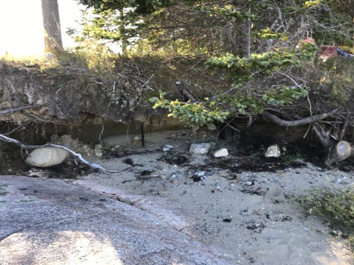
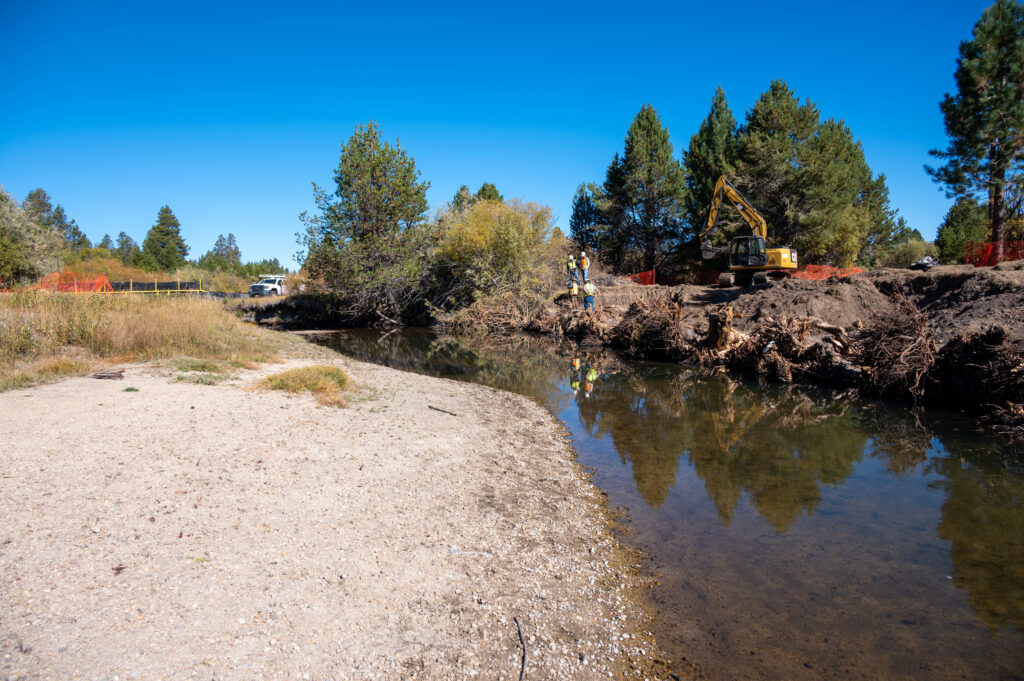
You are pleased that an adjoining, pristine creek has not been disturbed, but the weather report on your cell phone shows a thunderstorm headed your way before nightfall. What are you going to do? It is too late to phone for rescue by outside subcontractors, and they are already busy on another site — not your site.

You don’t have a potential problem — you have a real problem right now. However, if you have remembered the old Boy Scout motto, “Be Prepared,” and stocked the right materials for your “rainy day,” you can protect the creek and the jobsite.

Figure 2. Portable fertilizer spreader for coverage of small areas.

Sizing Up a Problem

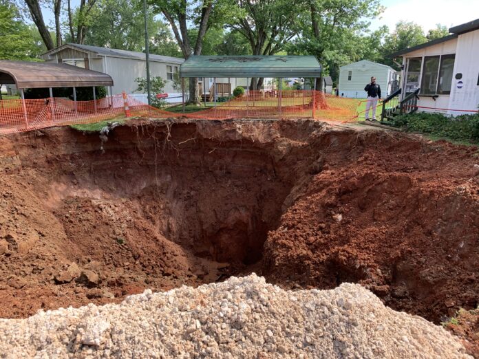
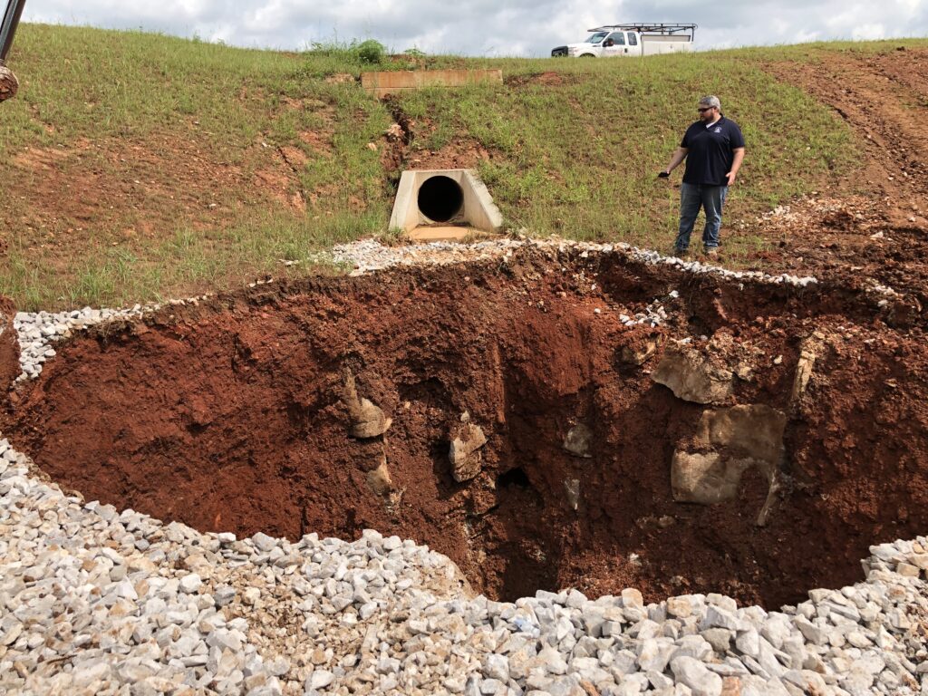
Some construction sites do not have erosion problems. They are the sites that have porous, sandy soils that can be addressed with mechanical practices such as sediment barriers (silt fences), berms or diversion ditches and filter dams.
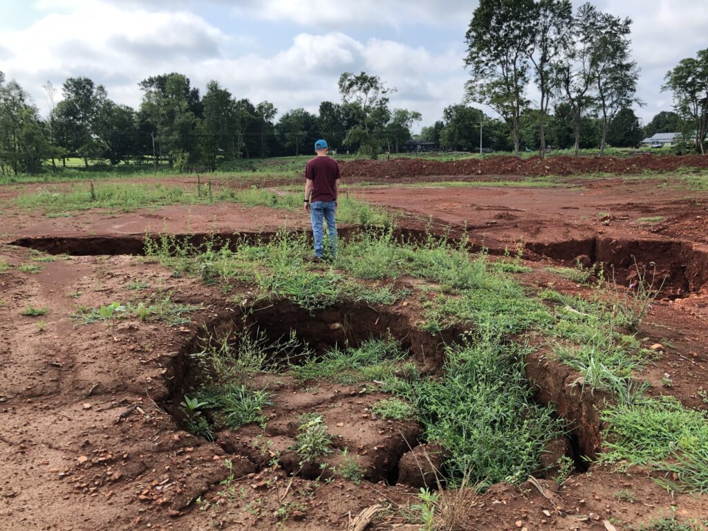
Other sites have a lot of clay in the soil. They have all the problems because clay-sized particles do not respond to mechanical or physical barriers. These cohesive soils do not provide good infiltration and thus promote surface runoff and erosion. The alternative for these clay soils is to use chemical practices offered by companies that specialize in using specific products. If they are not available, is there something you can do?

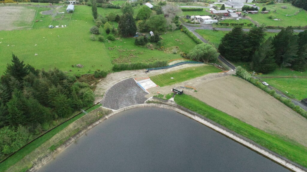
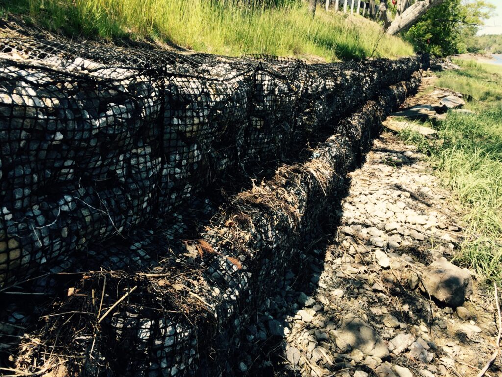
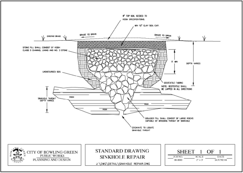
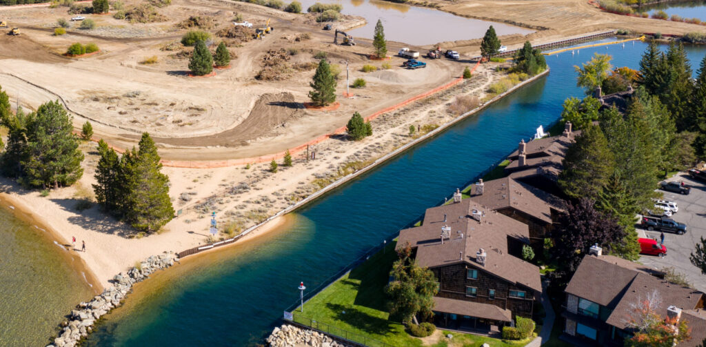
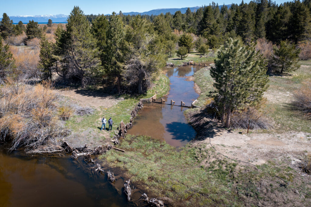
Yes, you can do it yourself, perhaps not perfectly, but enough to reduce the erosive problem until more help arrives on Monday. Maintaining a supply of erosion control polymer products can save time and money spent cleaning up the eroded stockpile of soil after the storm. Preparation includes researching polymer properties to know which products match best with your site conditions (Figure 1).

Figure 3. Leaf blower adapted to spread polymers over moderate-sized area.

Powder Polymer on Soil Surfaces

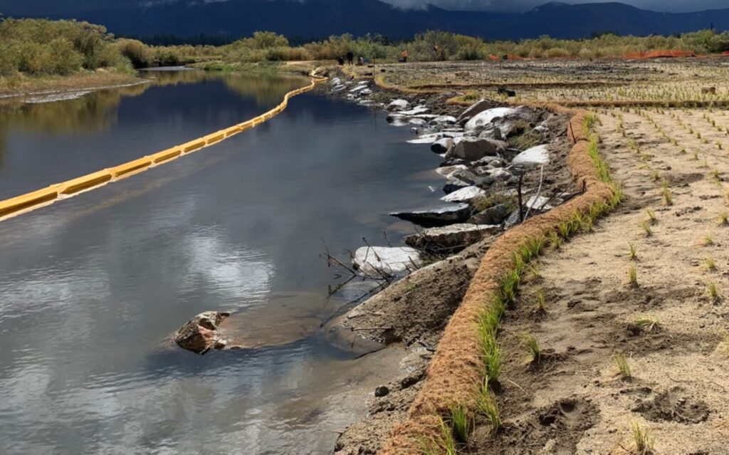
Hydrated polymers can create a micro-thin protective layer on the soil surface to reduce particle detachment by rainfall impact. Particles attached by polymers do not flow readily across the soil surface. For the most effective coverage, apply polymers from the bottom and the top of a slope.

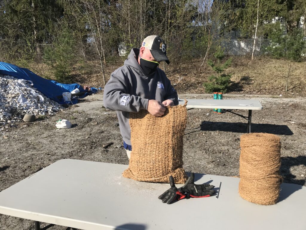
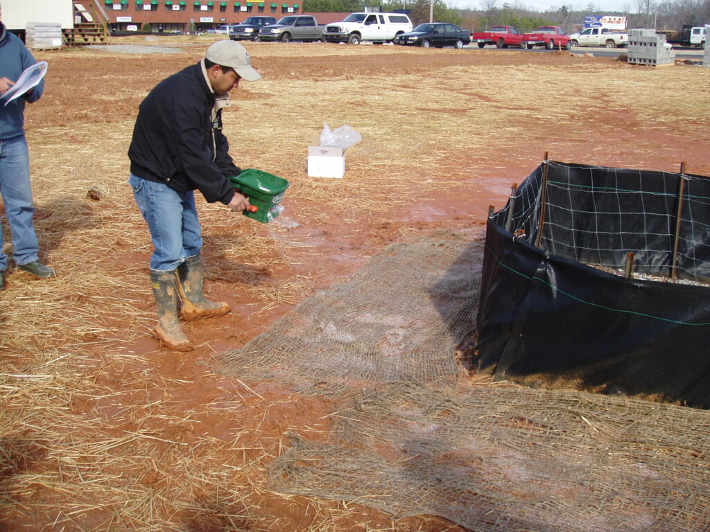
  • For small areas, a portable fertilizer spreader can be used (Figure 2). Proper clothing and protection is highly recommended to avoid skin and breathing problems. A retreating route is best for spreading powder polymer by hand on non-windy days.
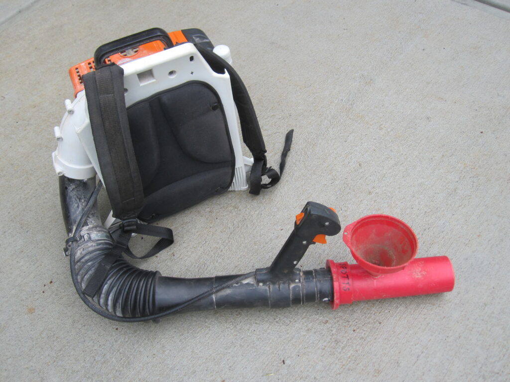
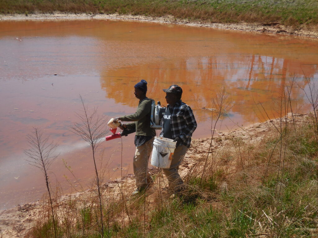
  • For moderate-sized areas, a funnel attached ahead of the trigger of a powered leaf blower is a good technique (Figure 3). To push the flour-like polymer a further distance, one portion of polymer should be premixed with four parts of dry sand. Be sure to create a venturi notch in the orifice of the funnel to prevent blow back of the polymer/sand into your face. Normally, this is a two-person technique. One loads the funnel with the powder/sand mix, and the operator triggers the blower tube toward the area to be covered (Figure 4).
Figure 4. A two-person team applies granular polymer for shore line stabilization.

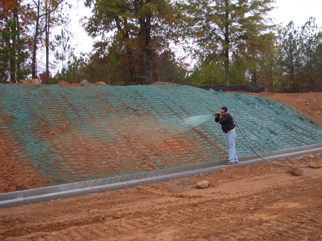
Liquid Polymer on Soil Surfaces

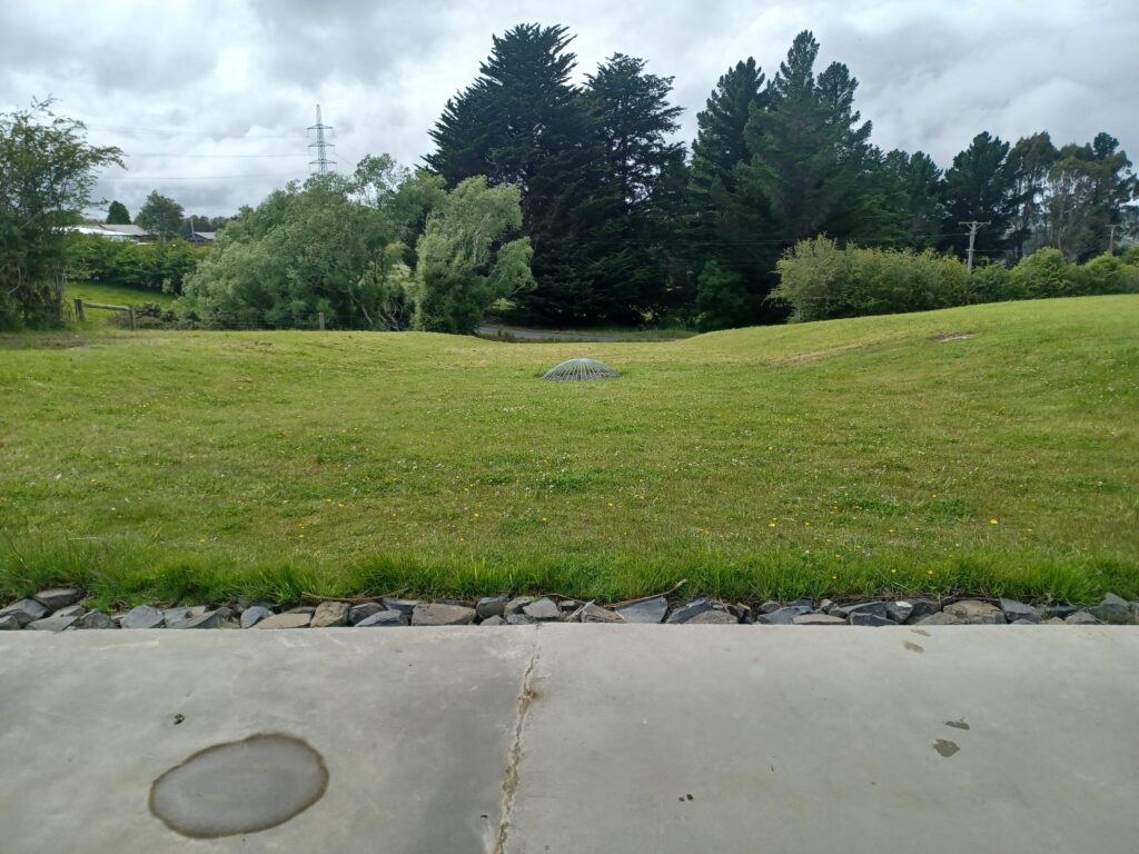
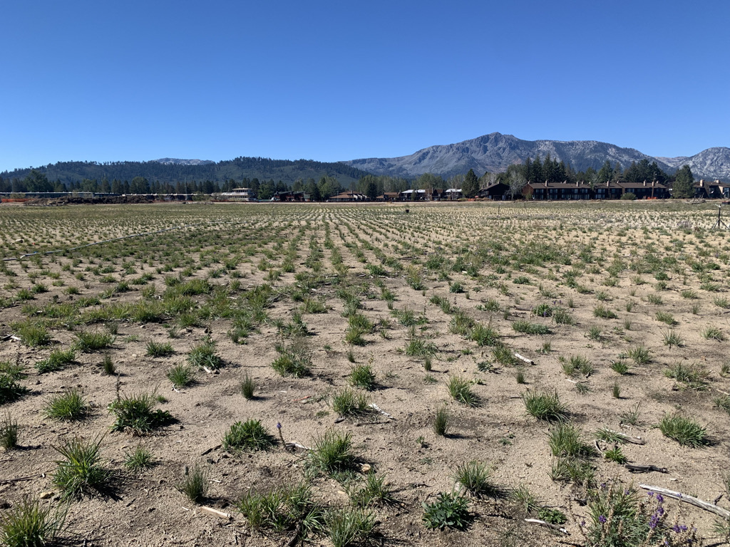
Manual application is time-consuming for very large areas and steep slopes. Liquid polymers are more commonly used separately or incorporated into hydroseeding applications (Figure 5). A secondary benefit is that the polymer will tack the seed in place until it germinates. If you attempt this technique, be sure to add the powder slowly into the circulating water in the tank. It will not dissolve if you dump it all at once. A wet application can be applied to reduce dust problems, especially on the shoulders
of roads.  

[Editor’s Note: This is the first article in a series of three that address the use of polymers for erosion control on jobsites. The next two articles will discuss polymer applications for ditches and channels and for quiescent ponds.]

About the Expert

James W. Spotts, M.S., Ph.D., CPSS, CPESC, is president of Southeast Environmental Consultant LLC. His company provides site inspections and NPDES discharge monitoring in the regional Atlanta area. Also known as “Dr. Dirt,” Spotts is passionate about sharing practical knowledge and teaching others how to solve field problems through demonstrations and class involvement.

Figure 5. Liquid polymers can be incorporated into hydroseeding applications.

Exploring Erosion of Reclaimed Coal Refuse Impoundments

Figure 1. Impoundment in partially reclaimed condition in 2020.

Disposed refuse material resulting from the preparation of mined coal is often deposited in coal refuse (tailings) impoundments. The coal refuse consists of a coarse fraction used to construct embankments and a fine refuse fraction that is deposited in the impoundment reservoir basin in a saturated slurry form. Often, these impoundments are redesigned during construction to accommodate additional waste, resulting in increased embankment heights and slurry depths.1

Inspection and monitoring frequency of impoundments decrease as the impoundment moves through the stages of active, inactive and abandoned (i.e., after closure and reclamation).1,2 During closure and reclamation, the impoundment surface is graded so that precipitation drains to the perimeter to prevent pool formation and a re-impounding condition. The surface is then covered and vegetated. Because companies have no liability for reclaimed impoundments after release, the closed facilities must remain stable over time.2

The closure rates of idled coal refuse impoundments are increasing. The reclaimed structures are engineered to limit erosion, prevent impounding water, and to lower landslide hazard potential. However, little is known about the potential of these sites as long-term sediment sources. The objectives of this work were to: i) estimate sediment detachment at a recently reclaimed impoundment, and ii) observe evidence of erosion at reclaimed impoundments.

Figure 2. Reclaimed impoundment locations. Impoundment included in both the WEPP modeling and field evaluation is indicated by yellow marker.


Estimations of Sediment Detachment

A 29-acre (12-ha) recently reclaimed coal refuse impoundment located in Barbour County, West Virginia was evaluated. The site has a mean elevation of approximately 470 m MSL (1,540 feet), is located within the Western Allegheny Plateau and has a mean annual precipitation of 122 cm (48 inches)3 (Figures 1 and 2).

Reclamation was completed in 2020 with a post mining land use of pasture; cattle grazing is expected in the future. The dam and surrounding terrain were cut and backfilled into the impounded fine coal refuse. The remainder of the dam crest and downstream slopes were set at a 2H:1V slope to maintain geotechnical stability, and a minimum 2% slope cap cover was placed on the backfilled impoundment to facilitate runoff. The depth of cover varied based on the bearing capacity of the fine refuse. A perimeter drain was added, and the site was seeded with a grass mixture (i.e., Dactylis glomerata, Lotus corniculatus, Trifolium pratense, Lolium multiflorum, Lespedeza bicolor and Triticum asetivum) following WVDEP4 guidance.

The reclaimed impoundment was characterized by field measurements. Slope was measured as 2.4% using a clinometer, and average ground cover was measured as 80.5% following guidance by Hopkinson et al.5 Composite soil samples of the top 6 inches (15.2 cm) of cover were analyzed for particle size distribution and texture classification (ASTM D2216, ASTM D854, ASTM D2487). The sandy loam had 55.0% sand, 19.8% very fine sand, 2.5% silt and 22.2% clay. Organic matter (OM = 3.9%) and cation-exchange capacity (CEC = 0.2 meq/100g) were determined by the WVU Soil Testing laboratory. Infiltration measurements were attempted; however, no measurements were possible because the site was saturated during each visit.

Sediment detachment was evaluated using the Water Erosion Prediction Project (WEPP) model with field-measured informed input parameters. Using TR-55 single storm predictions, the annual soil detachment was predicted to be 0.4 to 2.5 tons for a 2- to 500-year return period, respectively.

Then, 100 replications of the soil inputs were created, assuming normal distribution, for additional simulations (Figure 3). Sediment detachment and runoff were predicted at three slopes (2.4% as constructed, 4% and 5%) because impoundments are reclaimed with slopes to achieve drainage6, typically with low slopes. No differences in runoff were determined among varying slopes, but differences in soil detachment were predicted within the slope range of 2.4% to 5% (p ≤ 0.001); the 5% slope resulted in the greatest soil detachment.

Figure 3. Distribution of soil input parameters.
Figure 4. Summary of field observations of six reclaimed refuse impoundments.

Field Observations of Erosion

For the first five years after reclamation, a dam is considered capped/non-impounding, and regular inspections occur prior to terminating the dam license. Then, the dam may be properly abandoned with no required inspections.7 Six reclaimed coarse refuse impoundments were evaluated for evidence of erosion or instability during September 2021 through July 2022 (Figure 2).
During field observations, no evidence of geotechnical instability was observed, but there were observations of erosion (Figure 4). For example, surface water found a preferential path through roads (Figure 5a) or other areas, creating gullies. In addition, sediment was observed in ditches (Figure 5b), suggesting sediment detachment.

Uneven grading and saturated conditions of the slurry material were observed (Figures 5c, d), potentially indicating insufficient drainage. Long-term stability depends on the consolidation strength of the refuse material. The strength of fine coal refuse is sensitive to moisture contents, and liquefaction may be a concern.8,1


Conclusions

Model results and field observations of erosion at recently reclaimed coal refuse impoundments showed modest sediment movement, suggesting long-term erosion may not be a concern. Field observations of six reclaimed impoundments identified saturated near surface conditions, although no indications of large slurry consolidation leading to re-impounding of precipitation water were observed. Future work may consider evaluating additional and robust perimeter and down slope drainage structures like contact ditches to offset and minimize drain blockage or damage. 

Figure 5. Field observations: a) unconnected drainage, b) sediment in drainage, c) standing water and d) differential settlement.


References
Michael, P.R., M.W. Richmond, M.J. Superfesky, D.E. Stump, and L.K. Chavel. 2010. “Potential breakthroughs of impounded coal refuse slurry into underground mines.” Environmental and Engineering Geoscience, 16(2): 299-314.

National Research Council. 2002. Coal Waste Impoundments: Risks, Responses, and Alternatives. National Academy Press, Washington, D.C.

National Weather Service. 2020. “Local Climate Data and Plots.” National Oceanic and Atmospheric Administration, < https://www.weather.gov/rlx/climate> (accessed 3 March 2021).

West Virginia Department of Environmental Protection (WVDEP). 2016. Erosion and Sediment Control Best Management Practice Manual. Department of Environmental Protection, Division of Water and Waste Management, Washington, DC.

Hopkinson, L.C., E. Davis, and G. Hilvers. 2016. “Vegetation cover at right of way locations” Transportation Research Part D: Transport and Environment, 43: 28-39.

D’Appolonia Consulting Engineers. 2010. Engineering and Design Manual: Coal Refuse Disposal Facilities. U.S. Department of the Interior, Mine Safety and Health Administration.

Coal Related Dam Safety Rules. Title 38 38-4-21. 2003. https://dep.wv.gov/dmr/codes/Documents/Dam%20Safety%20Rules-2003.pdf (accessed 12 April 2023).

Huang, Y.H., J. Li, and G. Weeratunga, 1987. Strength and consolidation characteristics of fine-coal refuse. Annual report. United States.

Acknowledgements

This material is based upon work supported by the U.S. Geological Survey under Grant/Cooperative Agreement No. G16AP00091 and by OSM under Grant/Cooperative Agreement No. S21AC10058. Its contents are solely the responsibility of the authors and do not necessarily represent the official views of the USGS or OSM. This work was also in collaboration with the West Virginia Department of Environmental Protection.

About the Experts

Leslie Hopkinson, Ph.D., is an associate professor at West Virginia University. John Quaranta, Ph.D., PE, is an associate professor at West Virginia University. Sara Dalen, Brady Watters, and Titus Smith were graduate research assistants at West Virginia University, and Ethan Wimer was an undergraduate research assistant at West Virginia University.

How to Turn Good Ideas into Great Busine$$

It’s hard to believe we are more than halfway through 2023. I hope everyone reading this is feeling good about their people, profits and progress thus far. Remember, you really do control your own destiny. We may not control the weather or our competition, but we control what we put into the market that makes us unique and valuable in the eyes of our customers and stakeholders. Here’s how you can turn your good ideas into great business.

One good idea has the potential to springboard you to success you never dreamed possible, but just because it looks good on paper doesn’t mean it is good business. Your ideas are one of the greatest resources you possess, but most people don’t know how to monetize or convert them into unique and valuable assets.

The best way you can do that is to create a culture of what I call “ideation conversion” which simply means teaching your people how to turn their good ideas into tactical business resources that can make money and differentiate you from your competition.
Ideation is the process of forming ideas from conception. We’ve all had that spark of an idea and thought “Hey, I wonder if…,” but how many of us do something about those ideas? Start by writing the idea down while it’s fresh in your mind using a notepad, mobile phone or your laptop. Next, gather your team members who have different skill sets and roles together in a place where you won’t be interrupted and can share and shape your idea. Ask smart questions like, “How can this idea solve customers’ and stakeholders’ problems or give them a competitive advantage?” Remember that customers can be external or can be your internal team. You may have an idea that will recruit, retain and reward top talent!

Next, create a hypothesis around your idea and the product, process or service you’ve created. A hypothesis is a statement used to refute or validate your idea, and it ensures it is aligned with your business model and strategy. A hypothesis tests for three things.

  • Desirability. The new product, service or process is something stakeholders want.
  • Feasibility. It can be executed and managed.
  • Viability. It will make money for the company.

A good hypothesis will enhance your unique value proposition, identify a new strength and identify risks and opportunities associated with your idea. This leads to the next step, which is creating a simple experiment with the people who will benefit from this
new idea.

A good experiment helps reduce personal bias, risk and uncertainty. It produces weak or strong evidence to refute or support your hypothesis. It also defines your who, where and what and provides usable metrics that should objectively help determine success or failure. Examples include customer and stakeholder interviews or an email survey. You can also conduct a “day in the life of” experiment with a few of your best customers to see how your new idea fits into their business. Your business developers and key field people can solicit feedback from your customers, and you can conduct online research by using keywords to see if your idea has already generated news. You can also create a simple prototype or a call-to-action test by sending an email to customers or prospects asking them to click a link if they are interested in learning more.

Once you have the results of your tests, get back with your team to decide if more testing is needed, if changes are required, if the idea should be abandoned, or if should move forward with offering the new product, service or process. When done correctly many good ideas can be converted into great business. Go ahead, start generating some sparks.  

About the Expert
Judith M. Guido is the chairwoman and founder of Guido & Associates, a business management consulting firm in the erosion control and green industry. Guido can be reached at 818.800.0135 or judy@guidoassoc.com.

Factors in Erosion Control

Figure 1. Example of a moss biocrust on a slope. Photo credit: Rich McLaughlin.

Most folks involved in erosion and sediment control have an opinion about the most important factors in determining how well this is done on construction sites. Researchers in China conducted a study to quantify the opinions of 15 experts as to which factors, previously identified from the literature as being important, were the most important in minimizing soil erosion losses on construction sites.1
There were four categories of factors identified from published research: natural conditions (NC), construction activities (CA), conservation measures (CM) and management measures (MM). The NC factors were related to rain patterns, slope and soil, while the CA factors included cut-fill volumes and various water handling activities such as dewatering and vehicle mud removal. CM involved sediment trap design and maintenance and various measures to cover the soil. MM was overall site management from both the construction company and the government (regulations and inspections) sides.


This information was presented to 15 decision-makers that included 10 professors and five senior engineers with extensive experience in construction site management in three large cities in China. They were asked to rank the relative importance of the factors. Overall, nearly half of the soil loss risk lay within the MM realm, indicating that willingness to use good practices was the most important factor. Within MM, both construction company and government management were very important. The authors suggested that these are indications of the need for training of construction site staff as well as government oversight and enforcement.


The next most important factor was NC, governing 26% of the soil loss risk primarily due to rainfall intensity. Sediment basins and cover brought the CM factor in at third most important and CA was considered the least important at only 10% of the risk. The ranking of factors within the four categories was highly influenced by the location of the experts and conditions at those locations.

Slope Revegetation

Revegetating steep, eroded slopes is always a challenge. A recent study evaluated the vegetation and erosion potential five years after a site received a variety of treatments to establish vegetation and reduce erosion.2 After tillage, the treatments included seeding with two different plant species — Cynodon dactylon (C. dactylon) and Coreopsis basalis (C. basalis) — with or without biocrusts (Figure 1)
composed mainly of mosses (primarily Anoectangium stracheyanum). The biocrusts were established by harvesting nearby biocrusts, grinding and sieving the material and spreading on the plots. Urea fertilizer was applied annually at 125 kg ha-1.


Erosion was measured under a rainfall simulator on large blocks (0.6 m x 0.4 m x 0.2 m deep) that were excavated intact using a steel frame inserted into the soil. Three successive rainfall events were simulated at 30, 60 and 90 mm h-1. For both plant species, testing was done with biocrusts both with and without the plant canopy in place. Both species were also tested with no biocrust and the plant canopy removed (e.g. roots alone).


Lastly, tests included biocrusts alone, plots with the biocrusts removed and control plots from untreated areas with bare soil. Overall, biocrusts provided 67% cover and plants 43% to 65% cover in the combined plots, while biocrusts alone averaged 98% cover. Erosion relative to bare soil was reduced very little in the removed biocrust plots and 40% to 70% where only the plant roots were present. Plots with biocrusts with or without plants generally had erosion reductions of greater than 90%. Overall, biocrusts (moss) were the most effective at reducing erosion with or without plants, especially for the more intense rainfall events. The plant canopy was most effective during the low intensity event, but with decreased effectiveness at the higher intensities.


Both plants and biocrusts increased soil organic matter and aggregation and reduced bulk density relative to the bare soil controls. The authors suggest that short plants with dense canopies along with biocrusts are an excellent approach to reclaiming highly
degraded land similar to the red sandstone area with subtropical, monsoon climate where these tests were conducted.


References:
Tang, H., P. Shi, X. Fu. An analysis of soil erosion on construction sites in megacities using analytic hierarchy process. Sustainability 2023, 15, 1325. doi.org/10.3390/su15021325.
Shen Faxing, S., T. Chongjun, Z. Jichao, Y. Ronggang, Z. Taihui, and N. Dekui. 2023. Water erosion control of undisturbed soil cores by near soil surface factors after 5‑year vegetation restoration in red sandstone area from subtropical China. Journal of Soils and Sediments (2023) 23:1356–1369. doi.org/10.1007/s11368-022-03382-x.

About the Expert
Rich McLaughlin, Ph.D., received a B.S. in natural resource management at Virginia Tech and studied soils and soil chemistry at Purdue University for his master’s degree and doctoral degree. He has retired after 30 years as a professor and extension specialist in the Crop and Soil Sciences Department at North Carolina State University, specializing in erosion, sediment and turbidity control. He remains involved with the department as professor emeritus.

Dunedin’s Southern Reservoir Spillway Upgrade

Figure 1. The existing 1880’s constructed spillway.

Protecting the water supply for a New Zealand community was the goal of a reservoir spillway upgrade in 2019. Originally constructed in the 1880s, erosion and insufficient capacity of the original spill posed a risk to the future operations of the reservoir.

Dunedin is located on the southeast coast of the South Island of New Zealand and is known for its Scottish and Māori heritage.

Nestled in one of the hills above Dunedin is the Southern Reservoir Dam that was originally constructed in the 1880s and is owned and operated by Dunedin City Council, for the purposes of water supply. It has a total reservoir storage volume of approximately 260,000 cubic meters (340,067 cubic yards) at full supply level. Due to the condition of the existing spillway arrangement (Figure 1), it was recommended that a new spill be constructed in a location adjacent to where it currently exists.

An engineering report identified two confirmed dam safety deficiencies:

  • The existing service spillway, an appurtenant structure to the dam, has insufficient capacity to safely pass the required Inflow Design Flood. There is also a high risk of blockage, due to the culvert at the upstream end of the spillway.
  • Erosion of embankment materials around the existing service spillway location.

The new service spillway has been designed to safely pass the 1:10,000 Annual Exceedance Probability flood, and the new spillway must have a significant increase in capacity from 1 cubic meter per second (35 cubic feet per second) to 8 cubic meters per second (283 cubic feet per second).

Following an options assessment, a reinforced grass-lined spillway was selected as the preferred option. The key basis for this was capital cost versus other options such as concrete or rip rap. The cost of this solution was less than 50% the cost of hard armour, as well as providing a greener engineered solution. A key dam safety consideration for a grassed-line spillway is potential soil erodibility. Specifically, backward erosion (headcutting) leading to an undermining of the spillway control structure and an uncontrolled release of the reservoir. This meant the grassed spillway needed to be reinforced.

The five fundamentals of successful revegetation and erosion control was adopted and executed:

Figure 2. Hydraulic wood fibre mulch infill of the newly constructed spillway.

Fundamental #1: Understand Your Substrate.

A soil test was conducted with the soil that was to be used for the spillway. The results showed low levels of phosphorus and potassium. However, all other levels were in the ideal range to sustain vegetation. A fertiliser was selected to increase the levels that were deficient, to be applied with the hydraulic erosion control product (HECP) as well as the seed.

Fundamental #2: Species Selection.

Due to the Dunedin climate, only cool season grasses were selected. The average high temperature for Dunedin is 17°Celsius (63°Fahrenheit) in the summer months and 10°Celsius (50°Fahrenheit) in the winter months. Three of the four cultivars were bred within a 300 kilometre (186 mile) radius of where the project is located.

  • Colosseum perennial ryegrass (Lolium perenne) is a New Zealand bred turf ryegrass that provides exceptional winter growth and is proven to germinate down to soil temperatures of 5°Celsius (4°Fahrenheit) as well as being high in endophyte which helps to resist insect damage.
  • Governors creeping red fescue (Festuca rubra) was selected from naturalised fine fescue on the Banks Peninsula in Canterbury.
  • Arrowtown Browntop (Agrostis capillaris) was selected due to the plant having been bred from plant collections located in Arrowtown, Central Otago.

With the above three cultivars and the additional of a Silhouette chewings fescue (Fesctua rubra subsp. commutata) it meant the seed blend would be climatically adaptable to the project.

The blend consisted of (percentage measurements by weight):

  • 50% Colosseum perennial ryegrass (Lolium perenne).
  • 23% Governors creeping red fescue (Festuca rubra).
  • 22% Silhouette chewings fescue (Fesctua rubra subsp. commutata).
  • 5% Arrowtown browntop (Agrostis capillaris).
Figure 3. Vegetation establishment five weeks after installation.

Fundamental #3: Erosion Control Material.

A hybrid system consisting of a turf reinforcement mat (TRM) that is infilled with a hydraulic erosion control product was selected. The system offered a more aesthetically pleasing and environmentally superior means of protecting high-discharge waterways than the likes of concrete or riprap. The system begins with a TRM that provides a permanent, lofty and open matrix. It is then hydraulically infilled with a highly engineered wood fibre mulch (Figure 2) as a growth medium to intimately bond soil and seeds while accelerating growth and providing instant erosion control.

Fundamental #4: Correct Installation.

It was critical to ensure that the product was installed to manufacturers guidelines as well as to use a contractor with experience applying the hydraulically applied erosion control product was utilised.

The TRM was installed, then followed by:

  • Hydraulic erosion control product at 3,900 kg/ha (3,500 lb/ac).
  • Specified seed blend sown at 400 kg/ha (356 lb/ac).
  • Di-ammonium phosphate at 200 kg/ha (178 lb/ac).

Fundamental #5: Follow-up Inspections and Maintenance Practices.

The site was regularly inspected to ensure the success of establishment (Figures 3, 4). There was a fertiliser recommendation eight weeks after installation to encourage the speed of establishment due to the time frame that the spillway was required to be operational. This consisted of an application of a controlled released NPK granular fertiliser which had 70% upfront nitrogen and 30% slow-release nitrogen.

Once construction was completed and full vegetation was established, the project was then handed back to the Dunedin City Council’s operation department for maintenance such as mowing. The new upgraded spillway has been operational now for three years since its completion in 2019. 

About the Expert

Joe Johnson is the business development manager for PGG Wrightson Turf in New Zealand. He has been in the erosion and sediment control industry for 12 years and currently sits on the IECA Australasian Chapter’s Board of Directors as the Treasurer.

Figure 4. Two years after installation.

Meeting the Challenges of Rising Seas and Storm Surge

Figure 1. Shoreline degraded by rising seas and storm surge at Deer Isle, Maine.

Perspective
This article is part of IECA’s efforts to provide different perspectives on hot topics within, or that may directly affect, the industry. The purpose of these articles is to spark intrigue through dialogue as members of the industry consider their role in global issues.

Residents of Hampton Beach, New Hampshire received an early and very unwelcome holiday surprise on Friday, 23 December 2022. Wind and heavy rain swept toward the coastline. This was followed by a storm surge which resulted in substantial flooding of coastal property and infrastructure. This highly developed beach community, like many along the New England coast, was very hard hit.

The flooding began around 10 a.m. just before high tide was scheduled to hit. Things got much worse just 35 minutes later, when an astronomical high tide arrived with devastating fury. The seawall on Ocean Boulevard was overtopped by both surging tides and boulders.

Many local roads were quickly closed. A portion of U.S. Route 1 was closed between Hampton and Hampton Falls when a tidal marsh overflowed the roadway.

Fires broke out, and the flooded roadways made fire response difficult. Eight local fire departments provided support to the overwhelmed Hampton Fire Department.

Hampton Fire Chief Michael McMahon discussed the fires ignited during the flooding. “Motors and heating systems, compressors on refrigerators and electrical wiring can be operating correctly, but sea water is not good for this stuff.”1

Similar events are occurring all over the globe. Many in the scientific community have been warning that greenhouse emissions will result in significant climate warming which will lead to substantial glacial melt. As more water is released into our oceans, sea levels rise. This leads to more water in the atmosphere and storms growing more intense. As result, our coastlines are increasingly vulnerable to storm surge (Figure 1).

Figure 2. Assembly of shell bags for Maine Department of Environmental Protection living shoreline demonstration project in Brunswick, Maine. The shell bags were assembled using slow degrading coir fiber matting and containing clam shells.

An article published earlier this year in The Washington Post, authored by Brady Dennis, discussed the impact of extreme weather events in 2022. “The lessons we are learning from these more frequent, more costly extreme weather events should be apparent now across many regions,” said Adam Smith, a scientist with the National Oceanic Atmospheric Administration. “There’s no reason to believe that the trends will reverse or flat line.”2

Scientists agree that global warning will continue to accelerate unless humans significantly cut back on the greenhouse gas emissions that are heating up our planet.

Coastal communities around the globe are facing very difficult decisions. Regarding these issues, Suzanne Lettieri, a visiting architectural critic at Cornell University was quoted by Elizabeth Rush in her very engaging 2018 book, “Rising.” Lettieri said, “We have two choices, ‘raise or raze.’ You can either lift your home on stilts to allow the water to move under it or abandon the structure and move on.”3

In 2012, author John Englander published an important book, “High Tide on Main Street.” In this volume, Englander reviewed the facts regarding sea level rise and the importance of what he called “intelligent adaptation” going forward. Simply stated, Englander concluded that rapid sea level rise was going to continue and that that we simply must prepare to take the necessary steps to respond appropriately.

Those steps include planned abandonment of vulnerable areas, a most unpopular strategy. Such a plan is already in place for the village of Fairbourne, Wales, in the United Kingdom. Not surprisingly, the announcement of this plan was not well received by village residents, especially those with deep roots in the community. The government, taking a longer view, introduced this strategy after weighing the village’s projected vulnerability to future sea level rise.

The Indian Ocean island nation of The Maldives is faced with the possibility of total relocation. The entire country averages only about 4 feet above sea level. The concept of moving an entire nation to higher ground is hard to process, but in this case it is a very real possibility.

Abandonment, of course, is just one alternative to sea level rise and storm surge. In many vulnerable communities, homes are being elevated. In other cases, seawalls have been installed. In Saco, Maine, a highly vulnerable wastewater treatment plant was recently decommissioned and was replaced by a new facility on higher ground.

Living shoreline solutions offer a valuable set of tools to coastal planners. In 2016, the United States Army Corps of Engineers Permit #54 encouraged states to adopt living shoreline, or nature-based solutions, to help cope with rising seas and coastal erosion.

Technology is available to attenuate wave action and help accrete sediment and sand. While traditional solutions called for hard armoring or seawalls, living shoreline techniques aim to work in harmony with nature while offering coastal protection (Figures 2, 3). Living shorelines are also significantly more nature friendly than hard armor systems. Adoption of living shoreline methodology is experiencing rapid growth in the United States, a most positive development.

In the Netherlands, living shoreline methodology has been successfully practiced for three millennia. At long last, the world is starting to recognize the benefits the Dutch continually have gained from these practices over the past 1,500 years.

Nine years after publishing “High Tide on Main Street,” John Englander produced a sequel. His 2021 book, “Moving to Higher Ground,” simply states that sea level rise is now unstoppable, lamenting the inability of our governments to deliver any meaningful strategy or actions to reverse outcomes.

Figure 3. Marine mattress installation in Harpswell, Maine. Mattresses were installed to mitigate damage caused by rising seas/tidal surges in area.

Finding solutions for these serious environmental problems is the real challenge. In his second book, as the title suggests, Englander concluded that we must simply prepare to relocate to higher ground. He also had specific suggestions to finding solutions.

  1. Reduce CO2 emissions to slow the warming, the melting ice and rising sea.
  2. Prepare for more frequent flood events.
  3. Prepare for long-term sea level rise.
  4. Address the multitude of other critical environmental issues. These include clean air, safe drinking water, recycling, ending the scourge of plastics in our ocean, coral reef protection, wildlife and ecosystem conservation and restoration.4

The path forward is challenging and loaded with obstacles. Political leaders, by nature, tend to avoid issues that lack immediate urgency. Sea level rise is a long-term problem, while election cycles operate in a much tighter time frame. We simply cannot wait for government officials to take action. To successfully confront the serious implications of sea level rise, serious long range planning is essential. In the military, the three “Ts” are often discussed.

The words are training, teamwork and trust. Perhaps this approach will yield the best possible long term results.

  1. Training. Education is vitally important. An informed public can and will demand that government leaders take meaningful action on climate change.
  2. Teamwork. The entire developed world must work toward solving the long-term sea level rise problems that threaten our planet.
  3. Trust. Our common bond requires that we are honestly confront this significant challenge together.

We owe nothing less to future generations.

There are many pathways to getting involved in this vital work that include research, volunteerism and advocacy. Climate Ready Communities [climatereadycommunities.org] has published a free guide for building climate resilience. The Nature Conservancy [nature.org], which works worldwide on tackling climate change and protecting our oceans, is another excellent resource. Locally there are many government agencies and non-profits engaged in natural resource protection. There are abundant opportunities for volunteers to get involved with beach monitoring, living shorelines, education and more. 

References

Chiaramida, Angeljean. Hampton Beach: Fire Displaces Family, Flooded Homes, Floating Cars as Storm Surge Hits. 23 December 2022. Seacoast Online.

Dennis, Brady. Extreme Weather Took Its Toll on United States in 2022. The Washington Post. 30 December 2022.

Rush, Elizabeth. 2018. Rising. Milkweed Editions, Minneapolis, Minnesota. p. 78.

Englander, John. 2021. Moving to Higher Ground. The Science Bookshelf, Boca Raton, Florida. p. 168.

About the Expert

Peter M. Hanrahan, CPESC, is an independent consultant and has more than 44 years of industry experience. Peter has been an active member of the International Erosion Control Association since the mid-1990s and has served the organization in many roles.

Sinkhole Management in Kentucky: Strategies and Planned Assessments

Figure 1. A large sinkhole collapse in a residential area. Excavation has begun in the foreground.

Bowling Green, Kentucky, is a rapidly growing city of 75,000 people built entirely on a well-developed karst plain, upon which the natural drainage of the area flows to the Barren River via sinkholes, sinking streams, underground rivers, and caves developed in the underlying limestone.1 This natural hydrologic system presents a variety of challenges for development and urban planning, not least of which is the cover collapse sinkhole. Cover collapse sinkholes form when the soils overlying karst groundwater systems collapse into voids in the rock. These particular geohazards are common in the karst areas of Kentucky.2

As water moves into the underground streams carrying water through the area, it carries some of the soil into the caverns below. This creates a void beneath the surface but above the bedrock, supported only by the strength of the soil itself. Over time, the layer of soil between the void and the surface thins, and eventually it will collapse, leaving a steep-walled, hazardous hole in the ground (Figure 1).3 The size of these features can range from less than a meter to greater than 10 meters in diameter and depth, depending on soil thickness and the characteristics of the local bedrock.

Figure 2. Sinkhole collapse at the outfall of a stormwater quality unit in a retention basin.

Collapses are most commonly associated with rain events, which can make the local clay soils heavier and alters their mechanical properties. Another key factor in many cover collapse sinkholes is drainage infrastructure, which when compromised can cause water to pond or leak directly into the soil below surface (Figure 2). Many stormwater injection wells turn into sinkholes after clogging up, as water finds its way around the clogged hole into the groundwater system. Additionally, the removal of grass and other vegetation during construction decreases the strength of soil at the surface, and many collapses occur during the earthmoving phase of projects (Figure 3).

Per ordinance the city is responsible for repairing sinkholes occurring in the right of way of a city street or in a drainage easement within single or two family residential areas; in all other areas, the property owner is responsible for repairing the sinkhole. While some smaller sinkholes are repaired by city work crews, large ones are generally contracted out. Since 2016, the city has bid out a contract for sinkhole repairs every three years. More than 60 sinkholes have been repaired under the sinkhole contract. Additionally, sinkhole repair is a common corrective action noted in regulatory inspections of commercial stormwater infrastructure.

Figure 3. Interconnected sinkhole collapses at a subdivision during mass grading.

Most repairs performed are some variation of the concept shown in Figure 4:

  • The sinkhole is excavated until the “throat” (the hole in the bedrock that water and soil are flowing into) is exposed.
  • The sides of the hole are enlarged to remove all unstable material (commonly called the “wash”).
  • Geotextile fabric is used to cover all exposed soil in the excavated pit.
  • Crushed stone, beginning with boulders large enough to not fall into the throat, is added to the hole.
  • The size of rock added is decreased as the hole is filled toward the surface and compacted with heavy equipment.
  • Once the stone infill is near the adjacent grade, the fabric can be closed to encapsulate the stone “plug” and then either clay or topsoil can be placed over it, or a run of smaller stone to ensure drainage.
Figure 4. City of Bowling Green standard drawing for sinkhole repairs.
Figure 5. City-County Planning Commission Standard Detail for improved sinkhole drains.

One of the realities of drainage work in karst areas is the lack of surface streams to convey stormwater runoff. In order to mimic the natural hydrologic system, the city and developers often drill stormwater injection wells to route runoff into the subsurface, where it would have naturally drained to prior to construction of impervious surface areas. In most cases, a cover collapse sinkhole will outperform a drilled well and is thus desirable as a drainage feature. In one specific example, a drilled injection well accepted no water whatsoever, but a cover collapse sinkhole 150 meters away on the same property accepted 40L/s. In situations like these, the cover collapse sinkhole can be modified, or “improved” in our terminology, to serve as a stormwater injection structure. Figures 4 and 5 show the standard and improved sinkhole drain designs, but the structure can be modified to fit the situation. The intent of these structures is to utilize the natural feature for drainage while minimizing the erosive potential at the sink point. Many improved sinkhole drains have been in use for several decades (Figure 6).

Simpler methods of sinkhole repair see some limited usage. Filling the hole with coarse crushed stone (cobbles 15cm and larger) can in some cases stabilize a sinkhole and temporarily remediate the immediate hazard. Generally speaking, this does not resolve the issue — between settling of the stone into the caverns below to erosion of soil at the edge of the stone infill, this method is not a permanent solution. Another method of repair is to cap or plug the hole, either with compacted clay soil in 0.3-0.6m lifts or with concrete. This method can be effective as long as the water previously draining through the sinkhole has an alternate drainage path available, as in the case of sinkholes that form around clogged storm drains or leaking pipes once the infrastructure is repaired or unclogged. However, if water does not have a planned route out of the area, new drainage issues can ensue.

Figure 6. A sinkhole riser that has been in place in a residential drainage easement since the 1970s.

Many cover collapse sinkholes are preventable. Since these collapses often occur in areas recently cleared for development, minimizing development footprints can reduce the likelihood of a sinkhole collapse. Areas in which water stands for prolonged periods can also develop into cover collapse sinkholes; ensuring that stormwater is drained off to designated retention areas at least minimizes the occurrence outside of the retention basins. Additionally, regular maintenance of stormwater infrastructure to prevent clogging and leaks can reduce the likelihood of a cover collapse sinkhole.

To date, the city has not undertaken a comprehensive assessment of sinkhole repair methods. To rectify this, throughout the course of 2023, city staff will inspect all repairs previously completed under the sinkhole contract, as well as those performed as corrective actions to notices of violation in the same term. Once these inspections are completed, a report will be compiled and all appropriate guidance documents updated.  

References

Center for Cave and Karst Studies, 2006. “Karst Groundwater Flow in the Vicinity of Bowling Green, Kentucky.” Groundwater flow map prepared for municipal agencies of Bowling Green and Warren County, Kentucky.

Currens, JC, 2018. “Characteristics of Cover Collapse Sinkholes in Kentucky.” Kentucky Geological Survey Report of Investigations 3 (Series XIII).

Waltham, AC and Fookes, PG. 2005. “Engineering classification of karst ground conditions.” Speleogenesis and Evolution of Karst Aquifers, 3(1): 1 – 20.

About the Experts

Nick Lawhon, PG, CFM is the environmental compliance coordinator for Bowling Green (KY) Public Works, working primarily on MS4 and CVIW compliance, as well as being BGPW’s “holes-in-the-ground guy.” Courtenay Howell is the environmental compliance inspector for Bowling Green (KY) Public Works, focusing on construction site stormwater runoff compliance for the MS4 program. She serves on the IECA MS4 Management Education Track Committee and the Kentucky Stormwater Association Board of Directors.

Comprehensive, Synergistic Stormwater Channel Remediation

Figure 1. Outdated and eroded stormwater channel.

The Town of Big Flats, New York had a challenging series of stormwater channels on a public right-of-way. The series of stormwater channels transported rainwater and snowmelt that originated from a steep hill, crossed rights-of-way and eventually emptied into a stream. The long downhill run caused concentrated flows in the channels that temporary rolled erosion control products (RECPs) could not withstand. The decision was made to protect the land from erosion and scour by investing in a comprehensive overhaul of the failing stormwater channel system.

No modern best management practices (BMPs) were used in the original channel design, so property damage and maintenance problems occurred with each large rainfall and snowmelt event. Extensive soil erosion in the channels was an eyesore, and during large rain events, stormwater volume exceeded the containment capacity of the existing channels. To complicate matters, upstream channels that crossed private property were altered for aesthetic purposes over the years. These alterations significantly reduced the system’s ability to slow the water velocity entering the lower channels. The existing stormwater channels were lined with rip rap and had eroded swales approximately 4 feet (1.2 m) wide and 24 inches (61 cm) deep (Figure 1). A successful stormwater control plan using modern BMPs was needed to reduce the chance of damage to nearby properties.

Figure 2. Pollutant removal efficiencies for vegetated swales.1

Design Solutions

The benefits of vegetated channels or swales vs. riprap include improved contaminant filtration (Figure 2), flow velocity reduction, improved site access, lower carbon footprint and less destructive installations. For these reasons, engineers decided to use a vegetated channel solution that would carry runoff from the site and prevent the formation of gullies that deposit sediment further downstream. To do so, they incorporated several channel BMPs, including heavy-duty turf reinforcement mats (TRMs), scour protection mats, rock check dams and sediment retention ponds. Erosion control blankets (ECBs) were installed outside the main channels to protect the soil from erosion during rain and wind events and encourage vegetation growth.

Once final engineering and design solutions were approved for the site, the contractor began by implementing erosion and sediment control improvements. The contractor chose two American Excelsior products: a three-netted, fully synthetic TRM to line the stormwater channels and a straw ECB to line the sediment retention pond and protect other areas outside the channels.

As the first line of defense that covered most of the channel’s soil surface area, the TRM needed to be able to withstand whatever erosive forces it could potentially encounter.

Bound by three ultra-heavy-duty UV stabilized polypropylene nets, its matrix consists of 100% post-consumer recycled polyester fibers. Eighty percent of these fibers are greater than 5 inches (13 cm) in length, and all retain 95% memory of their original shape after loading via hydraulic events. Additionally, the fibers’ specific gravity is greater than 1.0, which means they do not float during hydraulic events. These characteristics allow the TRM to maintain its structural integrity and minimize erosive potential at the channel’s surface.

Scour protection mats were installed along with the TRMs to protect the outflows of stormwater culverts from plunge scour. Together, they worked to protect soil at such highly concentrated flow points from eroding and moving down the channel. Rock check dams were used to reduce flow velocity and consequently aid in vegetation establishment in the channel. Lastly, sediment retention ponds were strategically located to collect stormwater at the site.

Figure 3. Three-netted, fully synthetic TRM, new rock check dams and straw ECB created foundation for vegetated swale.

Executing the Plan

Existing channels were excavated, and the existing rock channel bottom was removed. The channels were then reshaped, deepened and widened to create more stormwater capacity and promote stormwater infiltration. After excavation was complete, the channels were compacted and fine-graded to remove any rills. The contractor ensured that the channel was free of obstructions such as tree roots, large rocks and other foreign objects, then evenly distributed topsoil at a depth of 4 inches (10 cm) to prepare for seeding.

After the channels were repaired and reshaped, they were seeded and fertilized. A cover crop of grain rye was applied at 20.0 lb/ac (22.4 kg/ha) and the specified upland low-growing wildflower-and-grass mix was applied at 30.0 lb/ac (33.6 kg/ha). After seeding was completed, the swales were lined with the three-netted TRM, and new rock check dams were installed on top of the TRM. Bare soil side slopes were seeded, fertilized and covered with straw ECBs (Figure 3).

Results

The design team recognized that the shear stress capability of vegetation alone would not survive the design flows of the channel. Therefore, the installation of the three-netted fully synthetic TRM was critical to successfully protecting the channel. It reinforced the newly established vegetation in the channel, allowing it to withstand future high-stress events and carry runoff away from the site. Coupled with scour protection mats at the culvert outflows, rock check dams, and sediment retention ponds downstream, the vegetated channel solution provided and continues to provide long-term protection for the site and surrounding area.

Meanwhile, the straw ECBs protected the soil that was disturbed outside the channels during construction. The resulting vegetation reduced the sediment load flowing to the newly established channels.

In total, more than 6,500 square yards (5,400 square meters) of the three-netted TRM and 3,000 square yards (2,500 square meters) of the straw ECB were used on the complex, ecologically sensitive 2-mile- (3-kilometer-) long project (Figure 4).

Lessons Learned

To meet the needs of the modern-day job site, it is imperative that professional project teams look for innovative solutions that, in most cases, will be a combination of multiple BMPs. Project team professionals must identify risks and understand the cost of failure. Every project, large or small, comes with a responsibility to find solutions that work to improve the environment. Modern BMPs, like the ones used on this project, allow for sites to be returned to natural conditions. They are better for water and wildlife and at the same time strong enough to protect our infrastructure. 

Figure 4. Completed vegetated swale.

Reference

Storm Water Technology Fact Sheet: Vegetated Swales. United States Environmental Protection Agency. Washington D.C. September 1999. Page 4.

About the Expert

Harvey Dickson, CPESC is employed by American Excelsior Company – Earth Science Division – Arlington, TX, as a territory manager of the Mid-Atlantic, New England, and Eastern Canada regions. He has over 16 years of experience in the erosion and sediment control industry and is vice president of the Northeast IECA chapter.

Restoration of Marsh Improves Water Quality and Wildlife Habitats

Figure 1. Map of the Upper Truckee Marsh restoration project.

Three years of construction and $11.5 million later, the residents of and visitors to the South Lake Tahoe area enjoy a newly-restored marsh that had been lost over the years following development and alterations to the river that flowed through it (Figure 1).

In the 1940s the Upper Truckee Marsh in South Lake Tahoe covered 1,600 acres, which made it the largest wetland in the Sierra Nevada. Water from the Upper Truckee River’s multiple channels and lagoons flowed into the marsh to Lake Tahoe.

The marsh began to change when ranchers manipulated the Upper Truckee River in order to dry out the marsh and increase forage for cattle grazing. In the 1960s, a large housing development bifurcated the marsh — reducing its size to 500 acres (202 ha).

In the late 1980s, further planned development of housing and a golf course on a portion of the remaining marsh was stopped by a lawsuit. The California Tahoe Conservancy, a state agency, purchased the property in 1988, with a plan to restore channels in the marsh and re-wet approximately 200 acres (81 ha) that dried out when the river was straightened. In the early 2000s, conservationists removed 8,000 truckloads of dirt that had been dumped into the marsh.

Designing the restoration project, which included filling a portion of the Tahoe Keys Marina that was called the sailing lagoon and restoring the area around it to create 12 acres (4.85 ha) of new wetland, required attention to the sequencing and scheduling of the work around the short construction season in the Sierra Nevada and the complex interactions of Lake Tahoe levels, the river and weather.

A public walking trail through the new wetlands to Lake Tahoe crossed the site and remained open for all but a few weeks during construction while it was upgraded (Figure 2). “It was interesting to have the public in the construction area, but we continually moved fencing and signage throughout the project to ensure safety of the walkers and the construction workers,” said Ed Wallace, PE, water resources engineer at Northwest Hydraulic Consultants.

“We spent a lot of time with the public, explaining what was happening and answering questions,” said Scott Carroll, senior environmental planner for the California Tahoe Conservancy, the project manager for the Upper Truckee Marsh Restoration. At first there was some mistrust and concern that the walking trail would be inaccessible, but the constant interaction allayed their fears, he added. “By the second year, they could see plants and progress on construction, and many stopped to watch construction from the trail.”

Figure 2. A public walking trail around the newly-constructed wetlands remained open.

Creating the new wetland required isolating the sailing lagoon from the Tahoe Keys Marina by constructing a sheetpile barrier between the two waterbodies. Fill placed for a future residential development was also removed and buried in the former sailing lagoon which also served to cover noxious plant species that had become well established in the lagoon. These noxious weeds were buried under two feet of material, then covered with a granular and sandy soil produced from grading. The new 12-acre (5-hectare) wetland area was shaped and contoured to elevations that would support a variety of wetland vegetation. Six species of sedges and rushes, willows, Woods’ rose and three species of currants were planted for erosion control and wildlife habitat (Figure 3, 4).

In addition to restoring a portion of the marina and surrounding fill to a wetland system, a key component of the project was the construction of channels to connect the river to the marsh and re-establish flows through historic channels, said Carroll.

Designing the channels in this project was difficult, said Wallace. “We laid out the channels to take advantage of existing channels and vegetation,” he said. “We placed the steep banks of the channel at the base of the vegetation, especially the large willows, which helped stabilize the bank and improved the habitat for wildlife.” Throughout the reconstruction of the channels, vegetation that was removed, pruned, and salvaged was stored onsite and used to stabilize channel banks (Figure 5).

Because the project spanned several years, it was important to stabilize all work and take steps to minimize erosion due to melting snow, rain and flooding river. The channels did activate a couple of times during storm events and during snowmelt but there were not significant amounts of flow. “For additional insurance and management, sluice boards (Figure 6), which can be operated manually, were designed and installed in the pilot channels to allow regulation of flows from the river and the channels, and allow the vegetation to become established before been connected to the Upper Truckee River,” said Julie Etra, MS, CPESC, Western Botanical Services Inc. “The channels were revegetated with a variety of biotechnical methods to stabilize the banks and provide habitat.” These methods included willow poles, fascines, clump salvage and replacement, wetland sod salvage and placement, container plantings (Woods’ rose) and branch packing to ensure well-stabilized slopes.

Figure 3. New wetland with plantings.

Species of plants were determined by hydrology and laid out by elevation and depth to groundwater, as well as availability. “In the 12-acre (5-hectare) new wetlands area, over 70,000 wetland plugs were planted because the area could not be left to natural recruitment, and most of these species typically don’t establish from seed,” said Etra.

Species that are dominant in the adjacent, undisturbed marsh and are commonly available and easy to propagate were selected for the new wetlands. The dominant species were a sedge and a rush, Carex nebrascensis (Nebraska sedge) and Juncus arcticus (Baltic rush). Others included C. utriculate (beaked sedge) C. pellita (wooly sedge), C. praegraclis (slender sedge), and J. ensifolius (equitant rush). Additional container plants were used to provide wildlife habitat, screening and pedestrian traffic control. Two seed mixes were also used to maximize diversity and erosion control, one for the uplands and transitional areas and the other for the wetlands. Seed quality was emphasized, with zero tolerance for weed species.

Figure 4. New wetlands one year after initial plantings.
Figure 5. Channel work in Upper Truckee Marsh.

Lake Tahoe Benefits From Restoration

Lake Tahoe’s average annual clarity in 2021 was 61 feet (18.5 m) compared to 63 feet (19m) in 2020, and the states of California and Nevada, which share a border at Lake Tahoe, are actively working to restore lake clarity to its historic 97.4 feet (29.7 m).1

The Upper Truckee Marsh is an important part of the Lake Tahoe ecosystem, said Carroll. “Previous residential and golf course construction activities in and around the Upper Truckee Marsh area were identified as major sources of sediment but the restoration of the marsh will filter more sediment, raise the groundwater table and improve the habitat for wildlife, fish and plants.”

All construction projects come with surprises, and this project was no exception. A pre-construction wildlife survey identified the presence of the Willow Fly Catcher, so construction was not planned in those areas during the nesting season. Beavers also added another layer of complexity in the design engineering phase.

“We conducted our site investigation a couple of years before construction to determine water levels and used that data to create the design,” said Brent Wolfe, PE, water resources engineer with Northwest Hydraulic Consultants. “Then, we discovered a significant increase in water elevation because some beavers had been very active in the time between our surveys and the start of construction. Luckily, it only affected one of the pilot channels, so what we planned as a secondary pilot channel became our primary channel.” 

Figure 6. New channels with sluice boards.

Reference:

Kerlin K. Lake Tahoe Clarity Report for 2021. July 06, 2022. www.ucdavis.edu/climate/news/lake-tahoe-clarity-report-2021

Funding for the Upper Truckee Marsh Restoration
The California Tahoe Conservancy provided funds from Propositions 12, 40, 50, 68, and 84, and from the Habitat Conservation Fund, with additional funding from the California Wildlife Conservation Board, the California Department of Fish and Wildlife, the USDA Forest Service, the U.S. Army Corps of Engineers, and the Bureau of Reclamation.

2023 Annual Conference

Sustained Contributor Award Winner Adam Dibble, CPESC, CESSWI featured with IECA President Jerry Sanders (left) and CEO, Samantha Roe.

2023 IECA Annual Conference and Expo

The 2023 IECA Annual Conference and Expo in Kansas City (KC), Missouri brought back our global community and a new group of peers to network with from the Geosynthetics group. The conference kicked off with a brews and BBQ tour of KC and ended with field tours of the Berkley waterfront development, smart sewer system and streetcar construction project. Attendees had plenty of opportunities to connect with new peers, learn and have fun!

Opening Keynote Session

The opening session, presented by Scott Mensing, PE, PMP and Colonel Travis Rayfield, PE, PMP, looked at the $529 million Kansas City, Missouri and Kansas Levee project which is one of the largest, most complex, civil works project that the U.S. Army Corps of Engineers – Kansas City District has delivered. The program will improve the reliability and resiliency of 17 miles of levees and floodwalls located along the Kansas River in the metropolitan area. When the project is completed in 2026, the KC Levees will reduce risk of flooding by 200%, improve the reliability and resiliency of the levee system, improve deteriorating and aging infrastructure, ensure “as-designed” performance during future floods and enhance levee safety and flood awareness.

IECA Recognizes Industry Leaders

The IECA Awards of Excellence program acknowledges outstanding achievements in the erosion and sediment control industry and is a staple event at the conference. This year’s recognized projects and leaders include:

  • The Kilométro 21, Vía Gigante-Garzón Recuperación, De La Banca Usando Megabolsas project received the Environmental Excellence Award which is IECA’s most prestigious award that recognizes excellence in natural resource conservation and environmental protection.
  • Peter Armstrong received the Outstanding Professional of the Year Award that recognizes an IECA member who demonstrates excellence in their work in the industry.
  • Adam Dibble, CPESC, CESSWI was presented with the Sustained Contributor Award for distinguished service to IECA and has made outstanding contributions to improve the erosion and sediment control industry for a sustained period of time.
  • The Auburn University – Stormwater Research Facility was awarded the Sustained Partner Award, which recognizes distinguished support to IECA and demonstrated long-term support to the industry.
  • Billur Kazaz, Ph.D. and Stefano Rignanese, M.Sc. were recipients of the Emerging Leaders Award (formerly the Young Professional Award), which recognizes outstanding young professionals under 40 years old in stormwater and erosion and/or sediment control projects, programs or academics that demonstrates excellence in natural resource conservation and environmental protection.

Expanded Expo Hall

This year’s Expo Hall included more than 300 exhibitors from the combined conferences showcasing the latest industry products and solutions. Attendees could attend both IECA Learning Zone (featuring Contractors’ Corner and vendor showcases) and Geosynthetics Learning Zone for additional training opportunities. The Expo Hall’s closing event “Taste of Kansas City” food stations provided samplings of famous Kansas City cuisine.

Poster Contest Winners

The poster presentations promote the exchange of scientific and technical information within the industry and are presented by students and young professionals. This year’s first place poster winner, Jannell E. Clampitt, EIT, CPESC-IT from Auburn University, presented “Materials Matter for Wattle Hydrologic Performance.” Megan Armstrong, from Auburn University, won second place with “Optimization of Sediment Basin Configurations.” Third place winner, Cheyenne Mata from Oklahoma State University, presented “Cost Assessment of Erosion and Sediment Controls Used by DOTs.”

Save the Date for 2024

The 2024 IECA Annual Conference will take place in Spokane, Washington, 25–28 February. The call for abstracts is now open and exhibition/sponsor opportunities are being sold for next year’s event
as well. 

MOST POPULAR