
Snow storage is a primary Low Salt Design consideration, yet it is an overlooked part of stormwater design. Snow typically melts at a rate and volume less than what is required
to design for rainfall and, therefore, is often overlooked, but some experts in the field are starting to awaken to opportunities for improving winter design. When snow storage is properly sized and located, and the meltwater footprint is controlled, safety is increased. Also, the need for salt is reduced. Less salt protects soil, vegetation and water, which is a core goal in erosion and sediment control.
Low Salt Infrastructure Design1 proactively improves winter safety and has great benefits to sustainability. Deicers, especially rock salt and other chloride-based ice melting chemicals, are used to clear ice and make pavement surfaces safer for travel. This strategy may seem efficient, but it is a costly, reactive approach to regain traction versus designing for winter. Salt applications over time lead to erodible soils, vegetation damage and increased infrastructure costs due to frequent repairs and replacements.
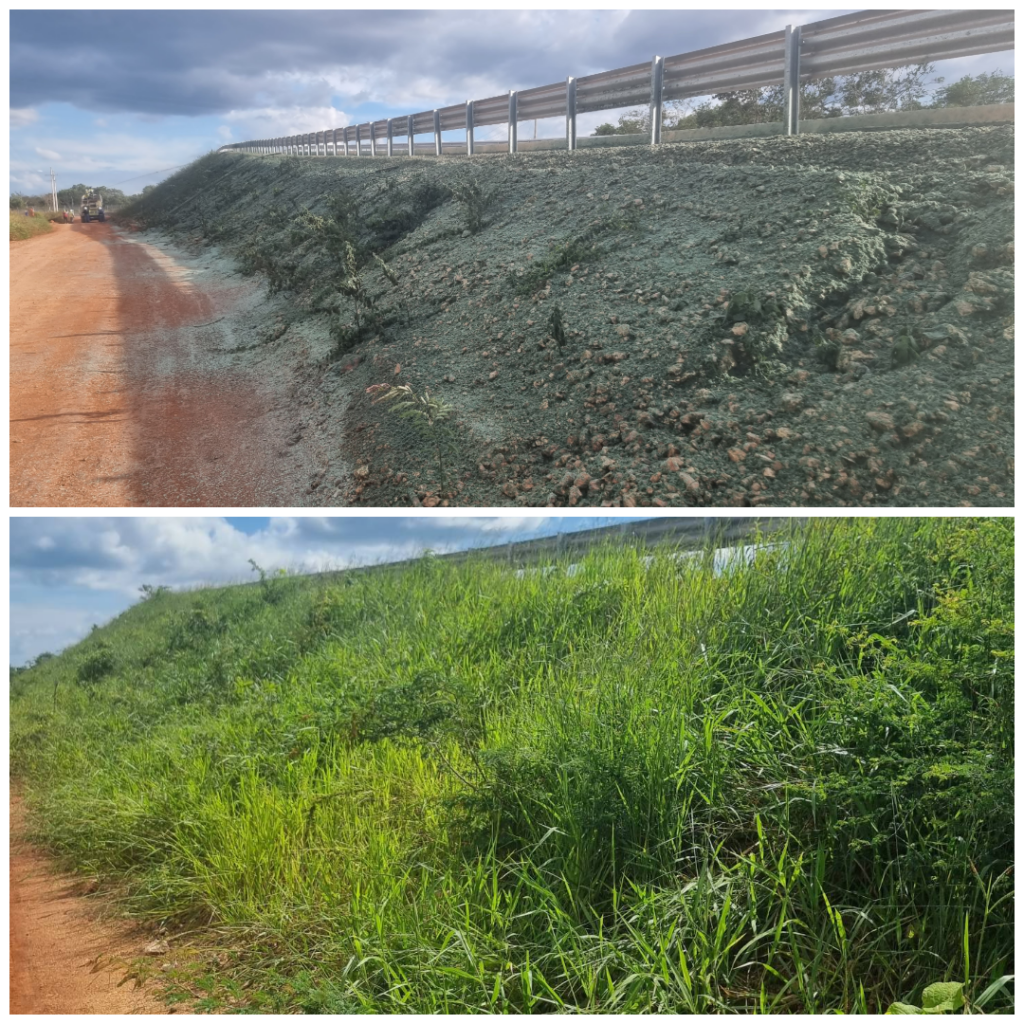
A wide range of Low Salt Design approaches can be implemented to help improve the performance of pavements during winter, which reduces the impact on the environment (Figure 1). “Use the Sun” by daylighting pavement areas to reduce winter shading, raise temperatures and remove moisture without maintenance crew intervention. Areas with poor winter performance may benefit from alternative pavements, such as heated or permeable. In regions where snowpack accumulates and wind generates snow drifts, consider the direction of prevailing winter winds and implement wind breaks in their path to
intercept and drop the blowing snow. Fences and/or vegetation can be designed to ensure
snow deposition occurs safely away from saltable surfaces.

Low Salt Design anticipates the impacts of winter weather and the need for winter maintenance throughout the design phases of a project, beginning early on. If a project is
geared toward improved winter performance, much less demand is placed on maintenance
teams.
Focus: Snow Storage
When snow blankets the landscape, it covers pavement surfaces and creates slick conditions for walking or driving. Maintenance professionals ensure the pavement is cleared
by plowing, shoveling, sweeping or snow blowing. Snow piles can take up space for months, which creates headaches and hazards of their own. The placement and footprint of
these piles can be designed to optimize many criteria that improve winter safety and drive down environmental side effects. Snow storage is a multifaceted topic that deserves a closer look.
Meltwater Sprawl
Snow and ice melting across pavement is bad news! In many areas, thaw-freeze transitions
far outnumber the occurrence of snowfall events. Maintenance crews have few tools to remove refrozen meltwater, so salting becomes more common wherever meltwater is allowed to sprawl and refreeze.
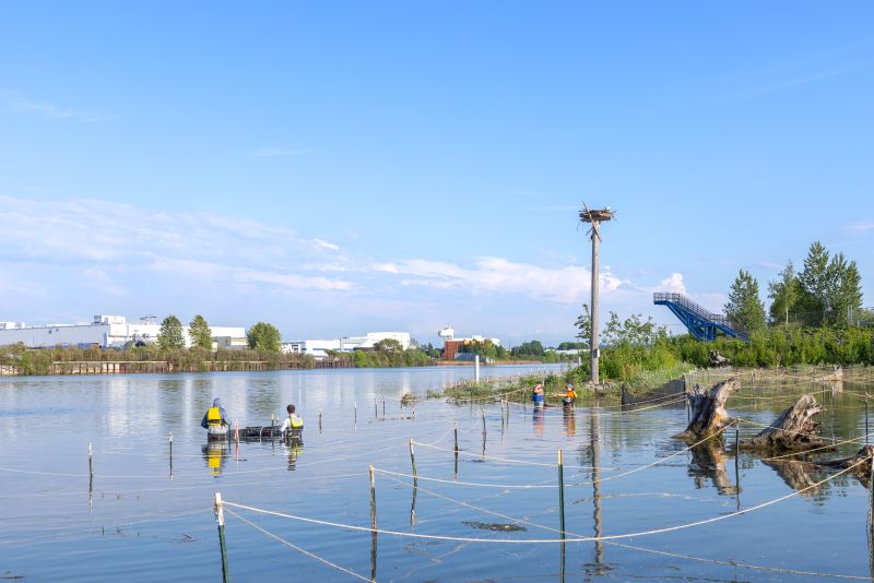
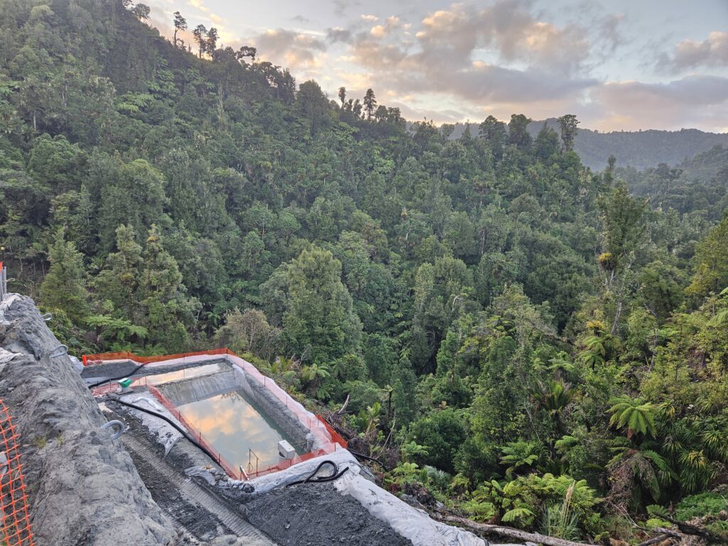
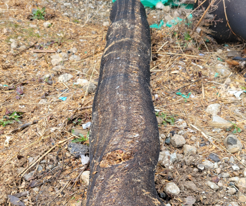
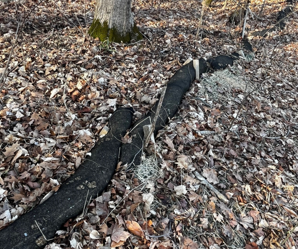
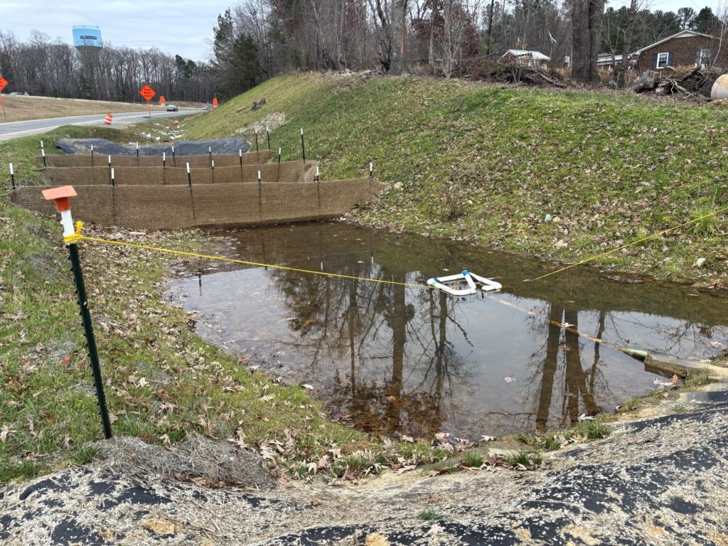
Place snow storage downhill from pavements or intercept and manage meltwater sprawl from snow storage located at higher elevations. Piles should drain into but not block stormwater conveyance (Figure 2).
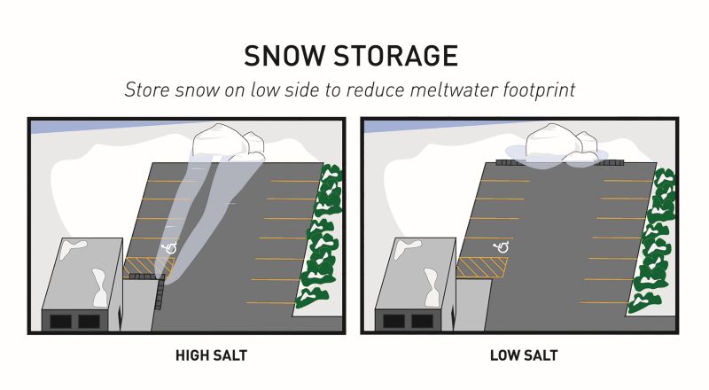
and less need for deicing chemicals.
Storage Sizing
How much storage space is necessary? Volume and density of snow are important factors. Snow-to-liquid ratios of fresh snowfall vary dramatically, but mechanically compacted snow can be considered as close to 2:1.2 A 6-inch snowfall on a half-acre lot is likely to produce anywhere from 1,400 to 2,200 cubic feet (39.64 to 62.30 m3) of plowed snow, depending on the initial density. Apply this half-acre example to an analysis of the past 10 years of seasonal snowfall accumulation data from NOAA’s National Operational Hydrologic Remote Sensing Center:3
- On the Front Range of Colorado, USA, Jefferson County averaged about 7.8 feet (2.38 m) of often fluffy snowfall per year, likely creating 22,000 cubic feet (622.97 m3) of plowed snow subject to many freeze/thaw cycles.
- Near the Twin Cities in Minnesota, USA, Hennepin County averaged 2.9 feet (0.88m) of snowfall, producing close to 9,700 cubic feet (0.27 m3) of pervasive plowed snow.
- Even in the hills above Asheville, North Carolina, USA, portions of Buncombe County logged multiple years with 1.5 feet (0.46 m) of snowfall, demanding room for 3,200 cubic feet (90.61 m3) of snow for at least short time periods.
Debris Recovery
Snow removal concentrates sand, grit and other solids throughout winter. Erosion control professionals know that these contaminants can quickly overwhelm otherwise adequate
stormwater systems. The excess loading of solids from winter quickly transitions to spring flash flooding. If snow storage isn’t intentional, sweeping becomes much harder. Debris recovery is less effective, and greater pressure will be placed on maintaining catch basins and ponds.
Well-designed snow storage provides an opportunity to recover winter debris with greater efficiency once the pile has melted.
Maintenance Equipment Accessibility and Ease of Snow Removal
If obstructions (signposts, railing footings, hydrants, parking lot islands and acute curb angles) make it difficult to plow, snow will be left in place or removed by hand. Snow on
pavement may be a liability concern. Hand shoveling means more time spent at a single
site, higher costs to maintenance operations and reduced overall effectiveness of snow removal efforts.
Hard-to-plow areas are much more likely to be treated with salt at higher rates to chemically remove residual snow. This manner of spot treating means high concentrations of salt, which corrode metal impediments. Toxicity to vegetation may become clear after only one or two seasons, and damage caused to brickwork or concrete won’t take much longer.
Snow storage should be designed with the route of the plow in mind, with easy forward
pushes and reduction of backup maneuvers.
The snow storage area should be obstacle-free, with no woody vegetation or permanent
structures like fixed outdoor seating.
Focus: Snow Storage Research Needs
This article shows that siting snow storage areas should follow somewhat simple logic.
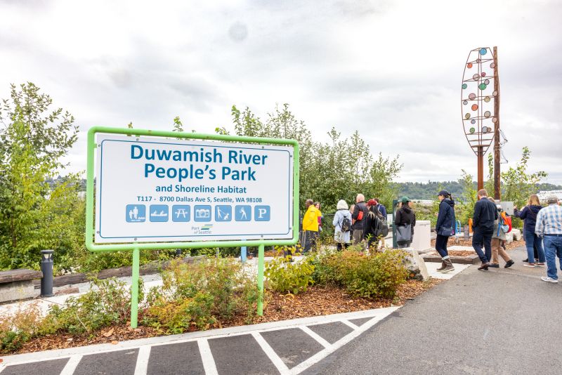
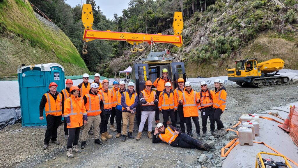
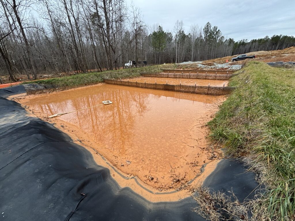
Issues arise when trying to answer the question: How big will my snow storage area need to be? Volumes discussed earlier don’t directly translate to a footprint. Failing to provide adequate snow storage creates a need for the snow to be hauled off-site (Figure 3). Snow science has historically focused on natural areas where snow is a water resource. Studies of snow in developed areas are far more limited. As a result, determining how much space should be dedicated to snow storage remains poorly understood.
Research is needed to evaluate influential relationships, including the ratio of contributing plowshed area to snow storage footprint. Annual or event-based snowfall amounts and frequency, and the rates of localized snow melting, are expected to influence the size of snow storage. The weight of these factors is yet unquantified, but this knowledge will be essential for designing cold-season stormwater practices on par with their warm-season counterparts.
Conclusion
Low Salt Design offers several approaches that improve winter safety and sustainability. Snow storage is one of many Low Salt Design considerations. Snow storage is complicated, and further research is needed, but it should become a cold climate design priority. Each region’s winter is unique, and understanding the problems faced locally will provide a safer and more sustainable future. To improve four-season sustainability, give winter a seat at the design table.
About the Experts
• Connie Fortin, Bolton & Menk’s low salt strategist, invented Low Salt Design to increase winter safety and drive down salt need. Forton has a Master of Science, and her expertise lies in chloride source reduction strategies, practical problem-solving and “simplifying science.”
• Doug Klimbal, a water resources scientist at Bolton & Menk, has knowledge that spans fields of resources and natural sciences, including environmental chemistry, hydrology and geology. He holds a Master of Science in water resources science from the University of Minnesota.
References
1. Bolton & Menk. 2024. Low Salt Design Guide. bolton-menk.com/real-solutions/low-salt-solutions.
2. Ho CLI, Valeo C. Observations of urban snow properties in Calgary, Canada. Hydrological Processes 19, 459-473. 2005.
3. National Operational Hydrologic Remote Sensing Center (2025). National Gridded Snowfall Analysis for Season Accumulation 2015 through 2025. NOAA. nohrsc.noaa.gov/snowfall.